This build log represents our attempt to build an L1 rocket that can fly on both 38mm motors and water.
The log is in chronological order so to see the most recent post you need to Jump To The Bottom. You may need to refresh this page to see any latest updates.
CAUTION: If you are going to attempt to build rockets such as these, please exercise extreme care when testing and flying them. This rocket uses very high pressures that can potentially cause severe injury to yourself and those around you. Always double check your equipment and review safety procedures before every test and flight. See more information on Safety Guidelines.
The rocket is mainly designed as a water rocket with an extra wide nozzle section that is also able to hold a solid rocket motor. This section will be referred to as the MMT (Motor Mount Tube)
Because the airframe is also a pressure chamber we will not be able to use the motor's ejection charge to get the laundry out and so we'll have to use electronic parachute deployment. We will use the same mechanism to deploy the parachute for both water and pyro modes of flight. For this reason we decided to purchase the StratoLogger CF from Perfectflite to record the flight and deploy a parachute at apogee.
This version of the rocket will be all fiberglass construction. We decided to use fiberglass only for this rocket. As this really is a prototype much like the original Shadow was. This will make construction a little easier and cheaper. As the pressure chamber will be only fiberglass the intended maximum launch pressure will be ~300psi. The point of this rocket is to achieve L1 certification with an H class motor and to be able to fly reasonably well as a water rocket. It is not intended to reach a specific altitude.
The motor mount is such that it can take 38mm motors of varying lengths. Initially it will be flown using a CTI 2-Grain case. The MMT is oversize on purpose so that we can wrap insulating material around the motor case to keep the heat away from the fiberglass. This will most likely be just cardboard.
The motor will not be sealed against the MMT to prevent over pressurization of the pressure chamber due to heat build up.
A separate insertable adaptor will be made that will seal against the inside of the MMT and fit the shadow nozzle.
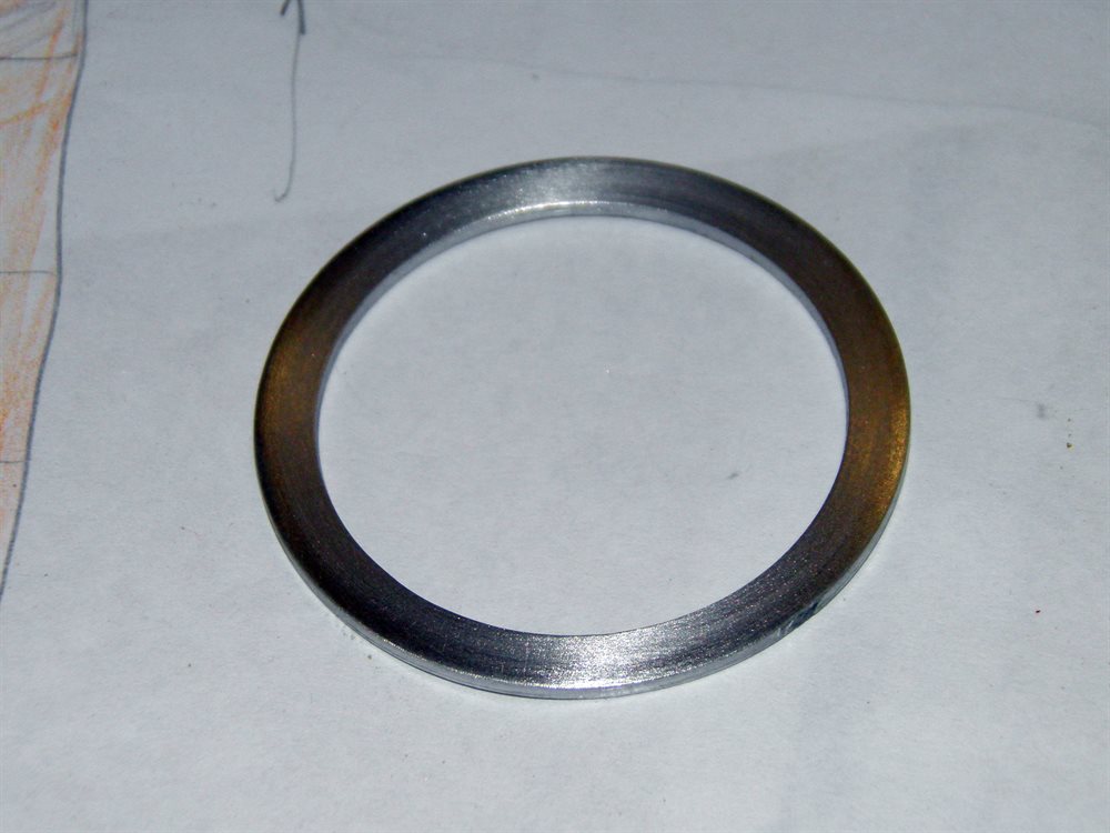
Both the nozzles adaptor and the motor will be retained by an aluminium threaded retainer. The other threaded ring will also be made of aluminium and glued to the outside of the MMT.
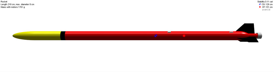
Here is an overall look of what the rocket should look like when built.
24 June 2016 - Started serious design and planning today. For this rocket it was decided that we are going to need to detect apogee rather than rely on timers. We ordered the StratoLogger CF and USB adaptor cable from PerfectFlite.
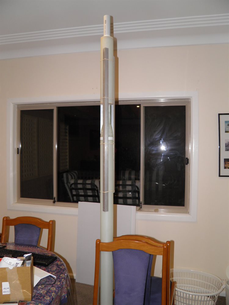
26 June 2016 - Bought 3m x 80mm PVC pipe from Bunnings to be used as a mandrel for the body tube. This is a thin wall PVC pipe used for down pipes.
7 July 2016 - Received StratoLogger and USB cable adaptor along with software.
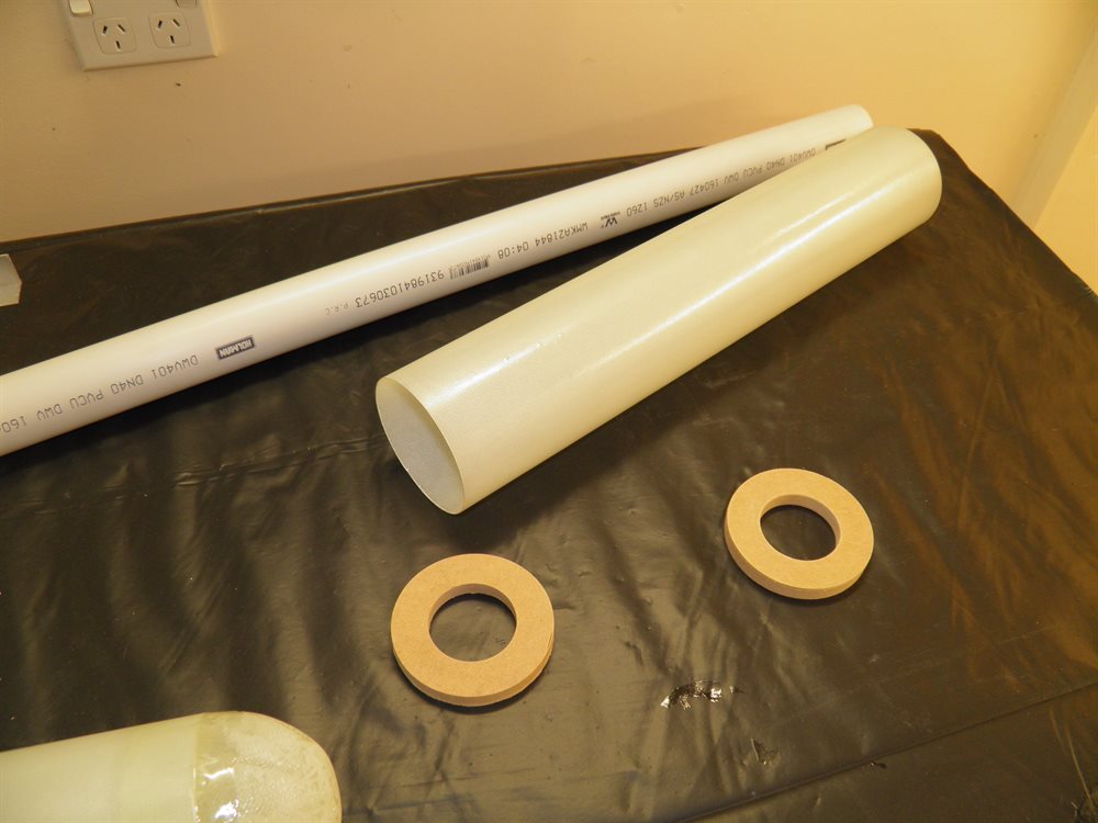
9 July 2016 - After doing research on the type of motors we will use, we decided to buy a 40mm PVC pipe to be used as mandrel for the MMT. We need this to be a bit wider than the normal MMT so we can wrap the motor in insulation so that it is not in direct contact with the hot motor.
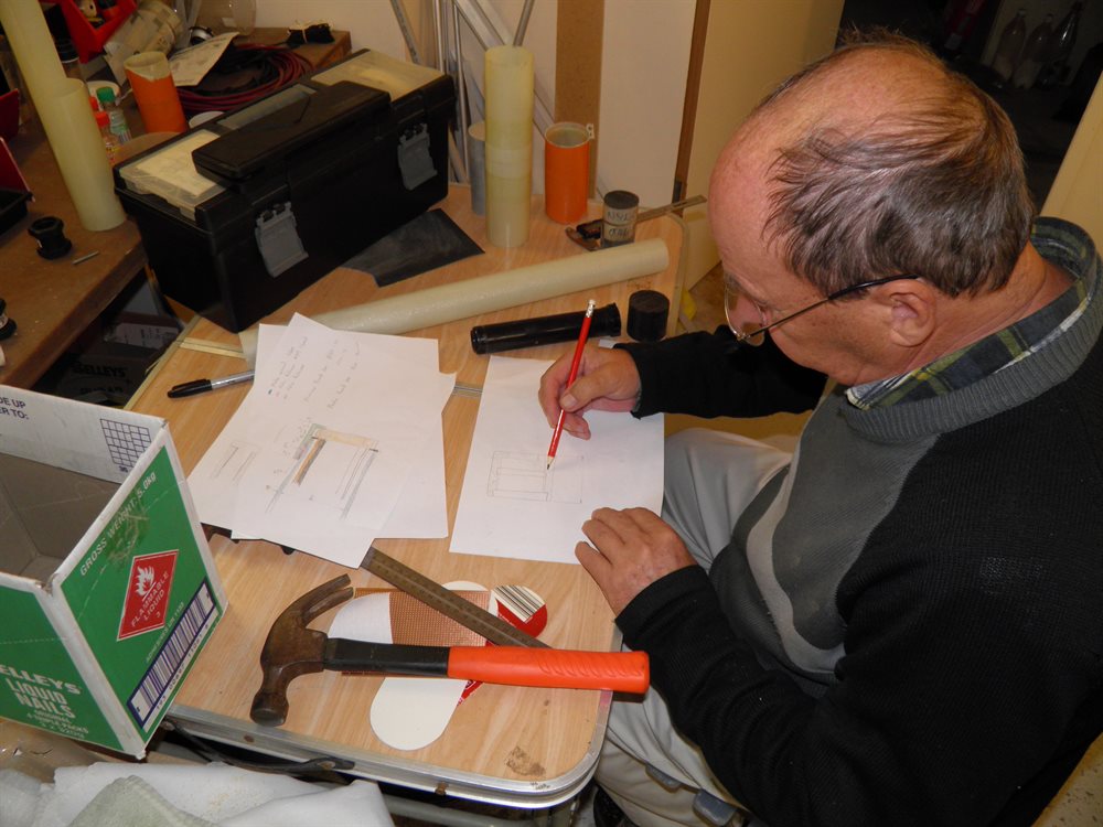
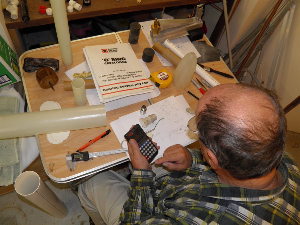
23 July 2016 - Dad and I spent some time designing the motor mount so that it will be able to house both the Dark Shadow nozzle adaptor as well as a 38mm CTI motor. We will make a thrust ring to fit at the aft end of the motor case. The length of the MMT is still yet to be determined.
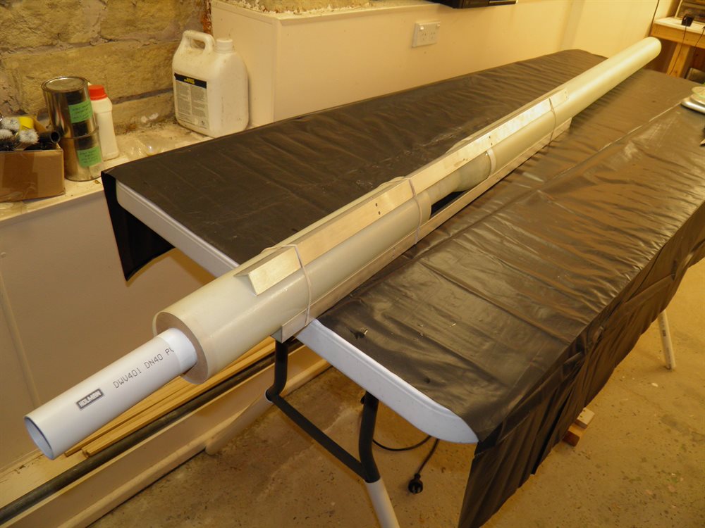
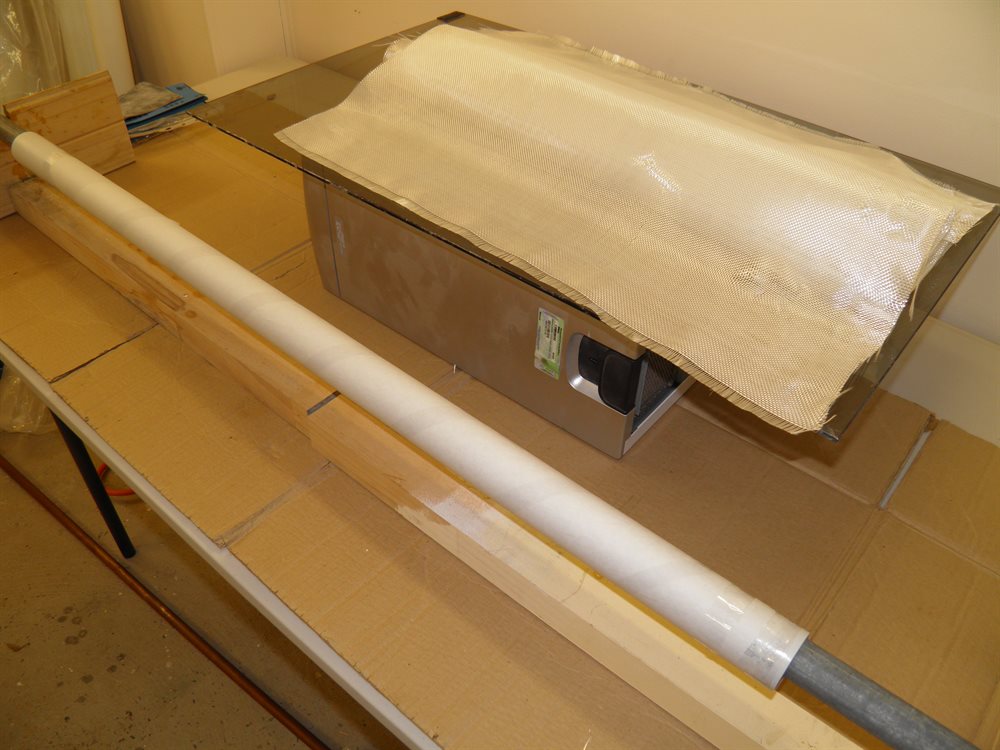
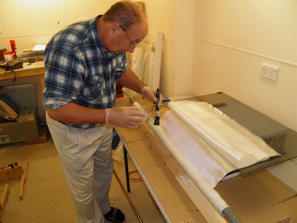
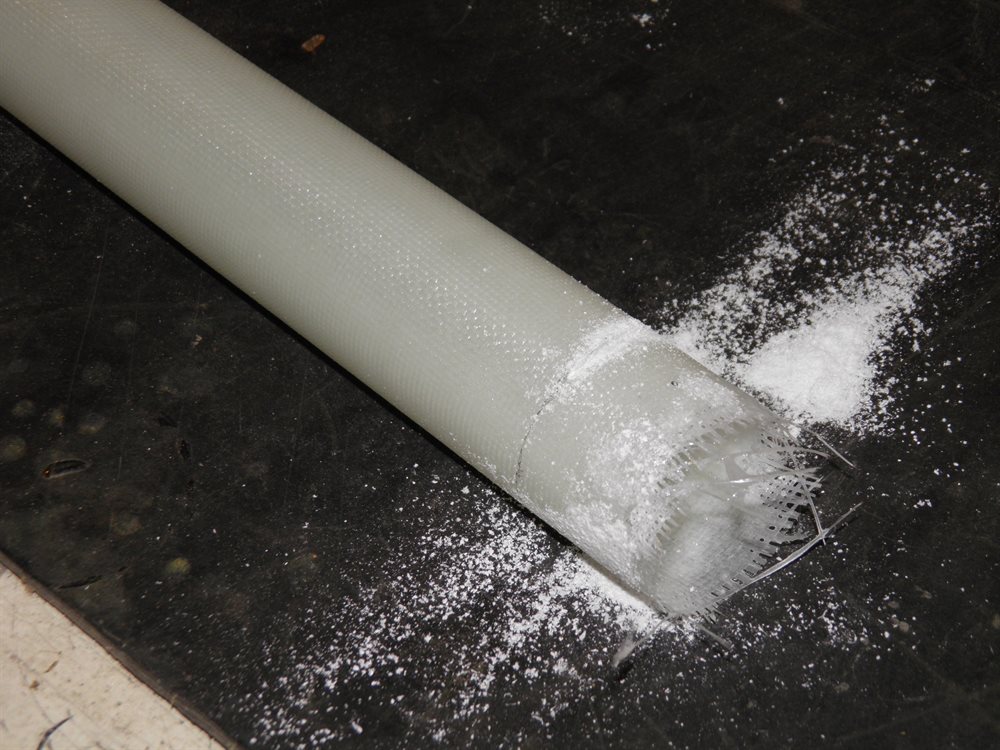
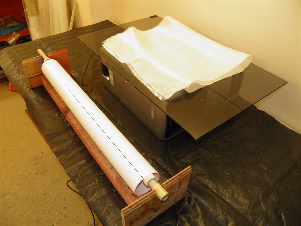
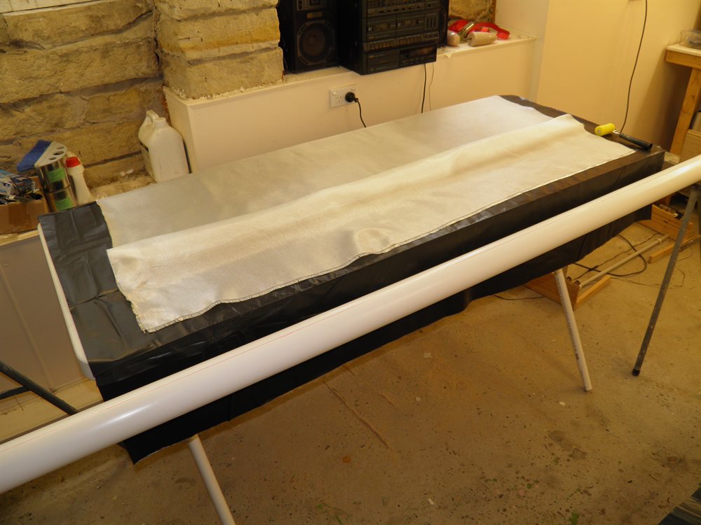
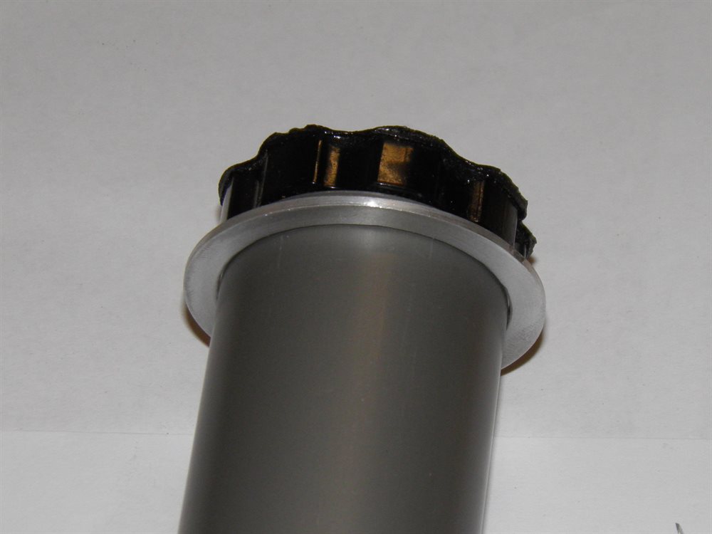
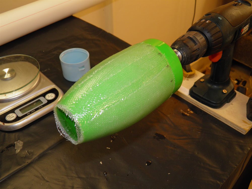
We wrapped the first prototype MMT out of regular 200gsm e-glass. We used 4 pumps of epoxy. The size of glass cloth was 450mm x 1000mm which gave around 7-8 wraps of the tube.
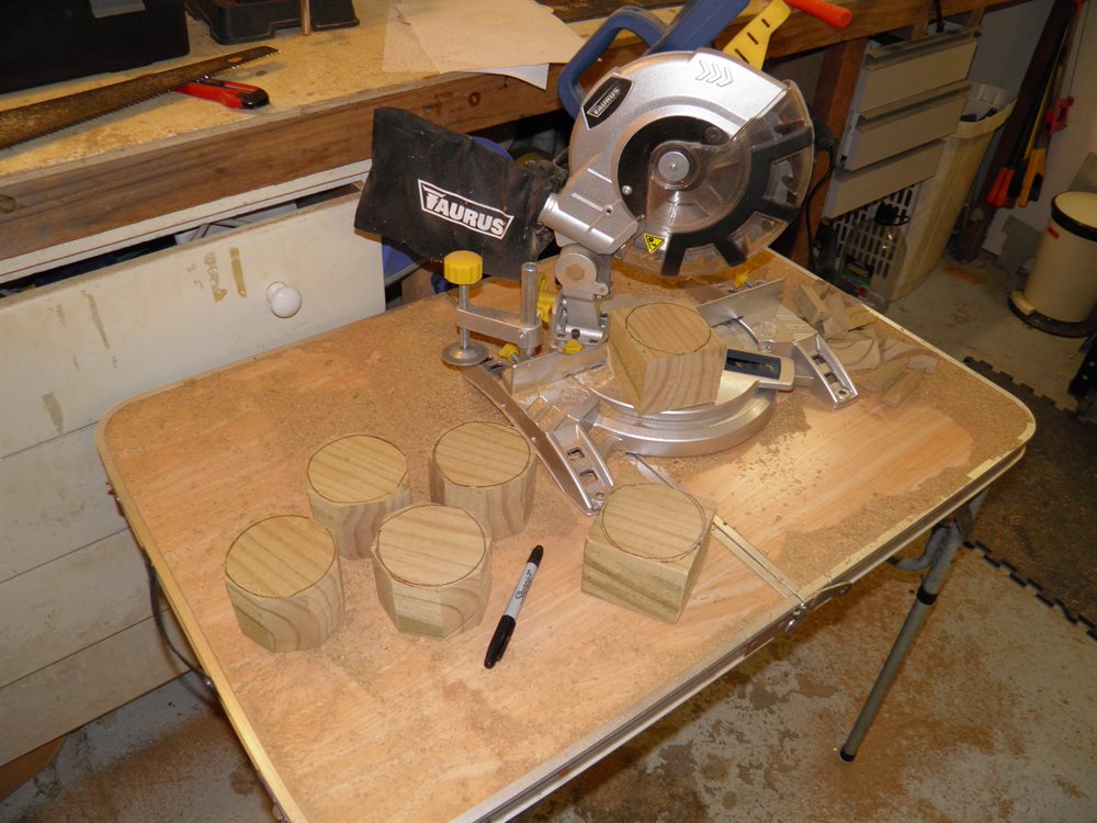
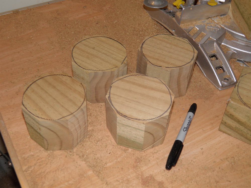
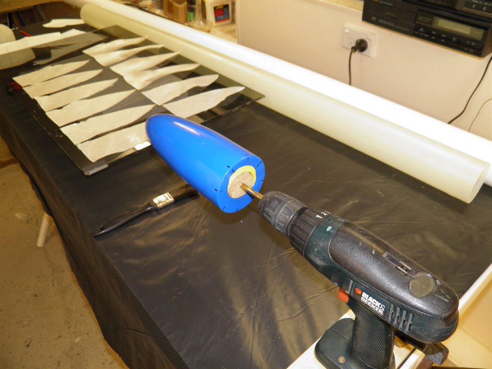
We cut and glued blocks of wood together that will be used to make the nosecone, forward closure and tailcone plugs. These are yet to be machined.
We decided to make the pressure chamber's cylindrical section 1.5m long. This should give us a total volume of around 7.7 Liters.


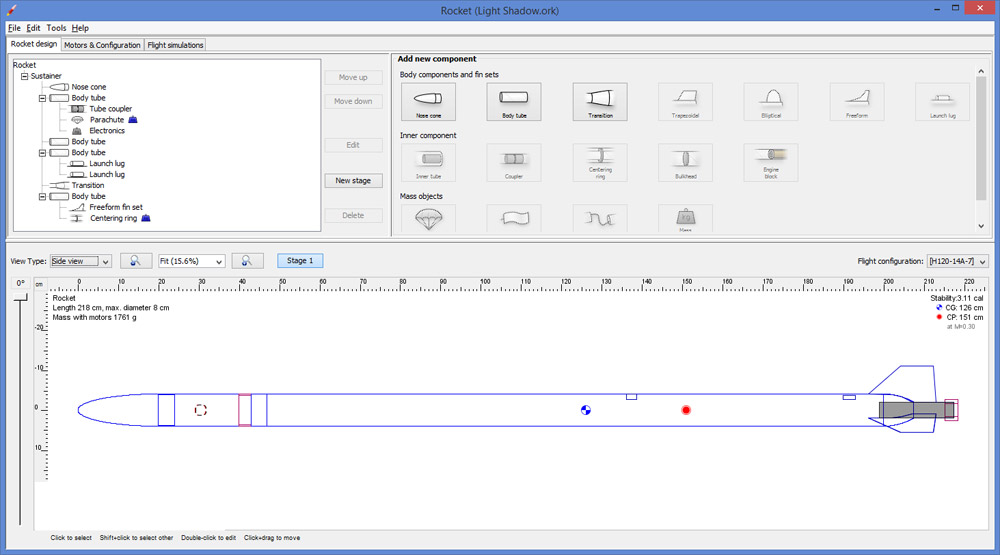
29 July 2016 - Running first simulations in OpenRocket to get an idea of the ball park performance expected. Max speed is around Mach 0.3 and max altitude is around 500m. Since we don't know the final weight yet, it's difficult to simulate with any great deal of accuracy. Entering the same spec rocket into Dean Wheeler's simulator we get an altitude of around 200m when launched at 300psi. We also decided that we are going to try this thing finished in the next 6 weeks in time for Mullaley.
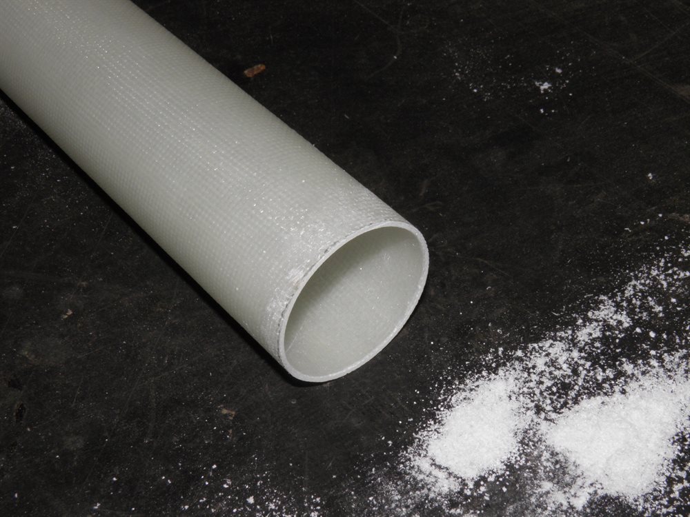
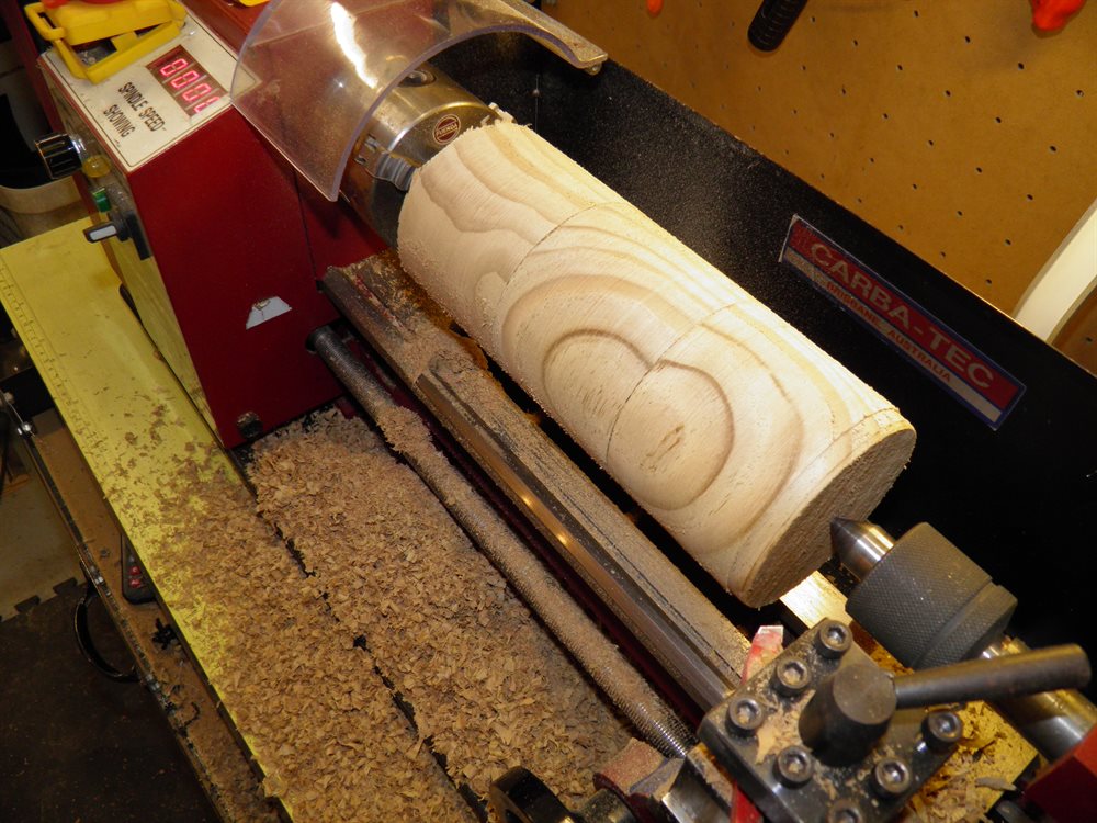
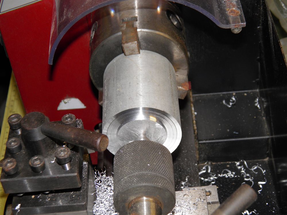
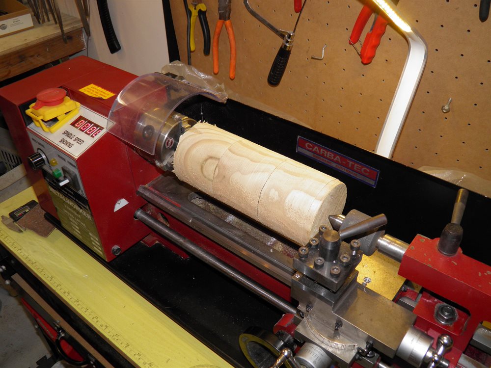
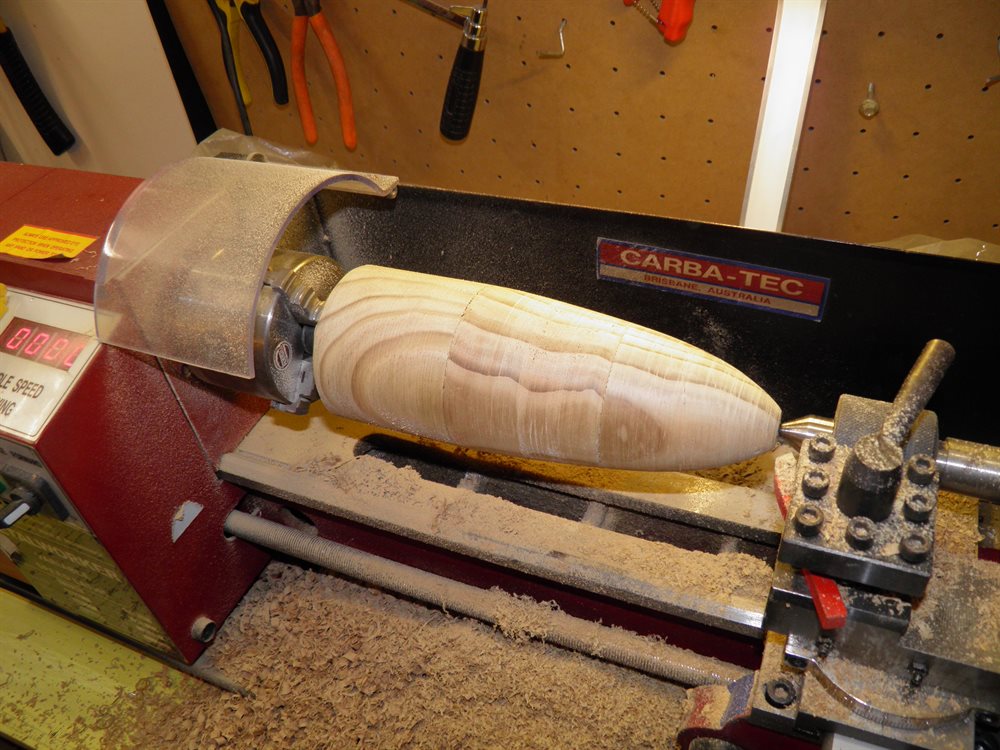
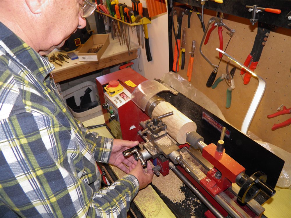
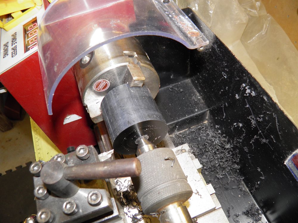
3 August 2016 - Removed fiberglass tube from mandrel and trimmed the ends of the MMT. We also attached the lathe adaptor to the nosecone plug blank and machined it down to about 85mm diameter. That is about the limit of what our small lathe can do. We also cut down the 80mm PVC mandrel to 2.3m long which will allow us to make 2m long tubes in the future though for this rocket the body will be 1.5m long.

4 August 2016 - We prepared the mandrels today for the body tube as well as the payload bay. We sanded the PVC tube with 800 grit sand paper to remove any bumps and nicks and then we used Carnauba wax to polish it. This makes it easier to pull the tube off when cured.

6 August 2016 - Made the payload bay tube today. This was also a prototype body tube construction test to see how stiff the rocket was going to be. We used 4 wraps of 200gsm cloth and 1 wrap of 85gsm cloth over the top. The cloth width was 450mm and we ended up using 3 pumps of epoxy for this.
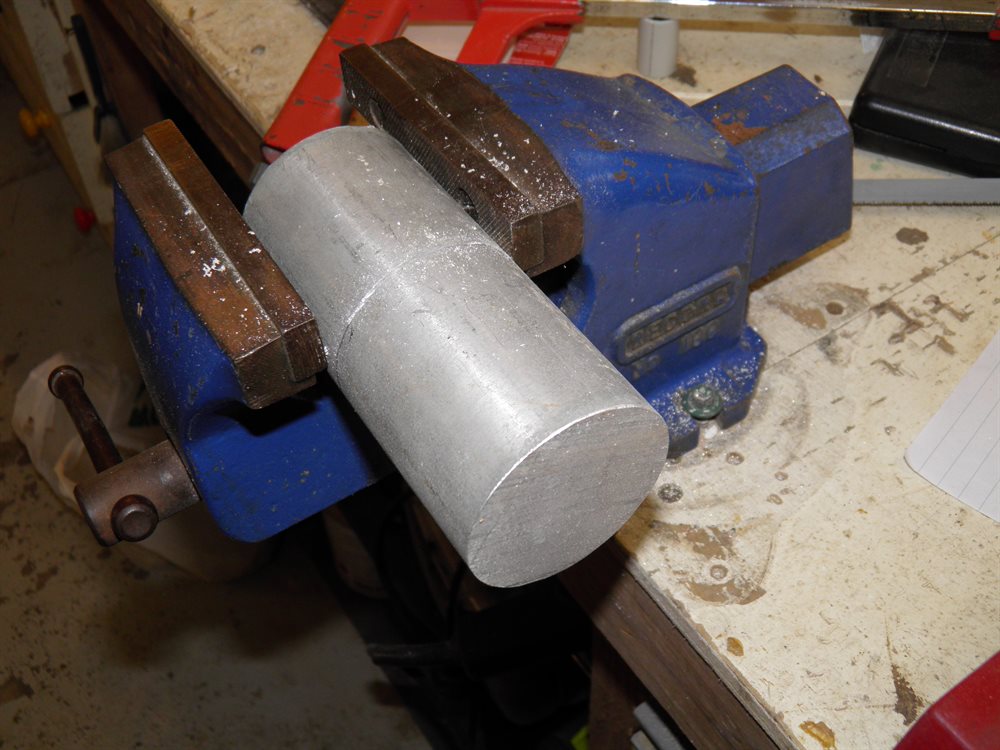
- We bought additional fiberglassing materials such as brushes and rollers as well as a 60mm x 600mm round aluminium machine bar.
7 August 2016 - Dad and I spent pretty much the whole day in the workshop today from 9am until 7pm.
- We trimmed the payload bay tube down to 42cm which weighs 151g. The tube didn't quite look solid enough for the pressure chamber and so we decided to add an extra layer of 85gsm cloth. If it turns out that the tube doesn't feel solid enough we may add another couple of wraps. Worst case scenario is that we will only fly it at a lower pressure since we are not after a specific altitude.
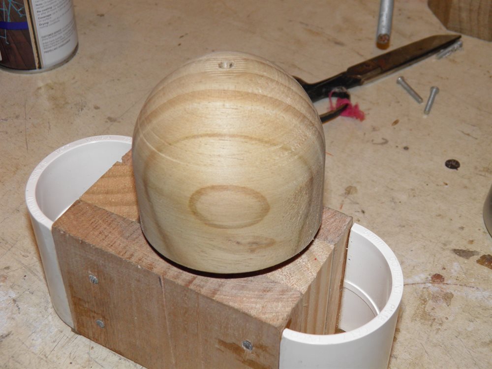
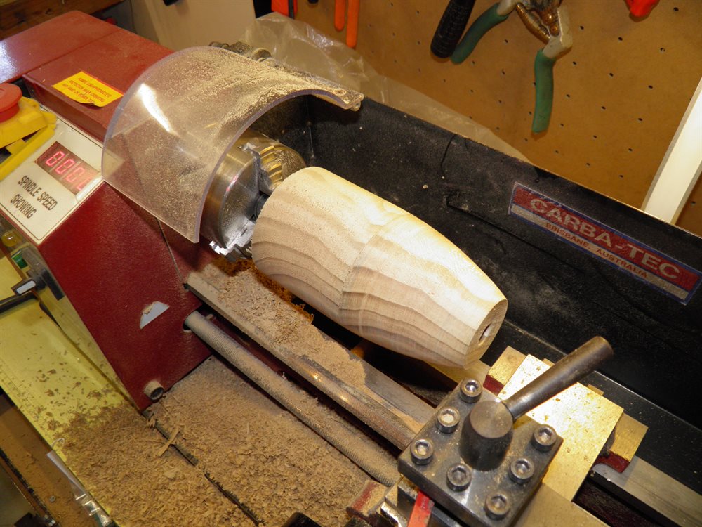
- Dad machined up the top closure plug from a piece of wood. The top of the closure is hemispherical to better distribute the pressure.
- We also rolled the main body tube today. We used 1m x 1.6m 200gsm cloth which gives us 4 wraps and then 1.6m x 54cm 85 gsm cloth over the top which gives us 2 and bit wraps. We ended up using 10 pumps for the entire body tube.
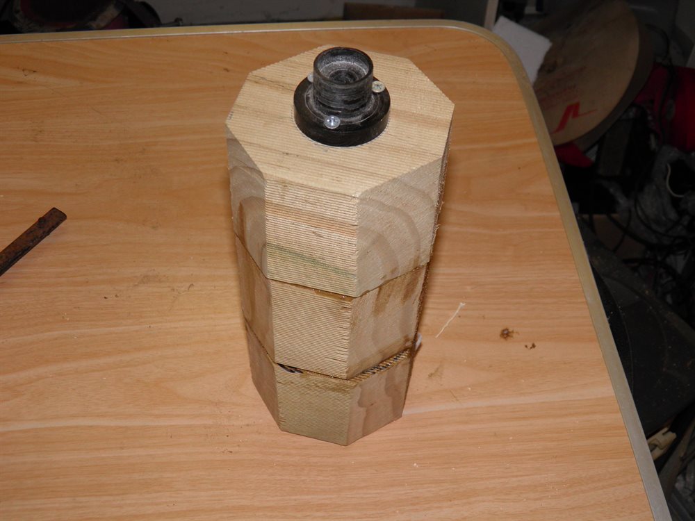
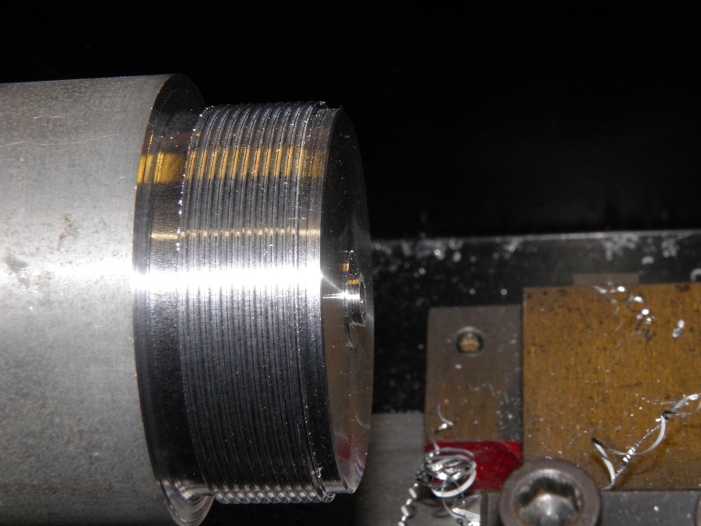
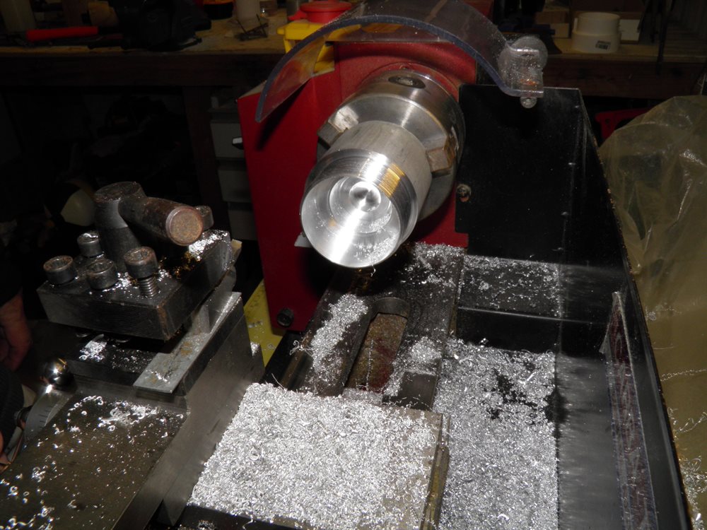
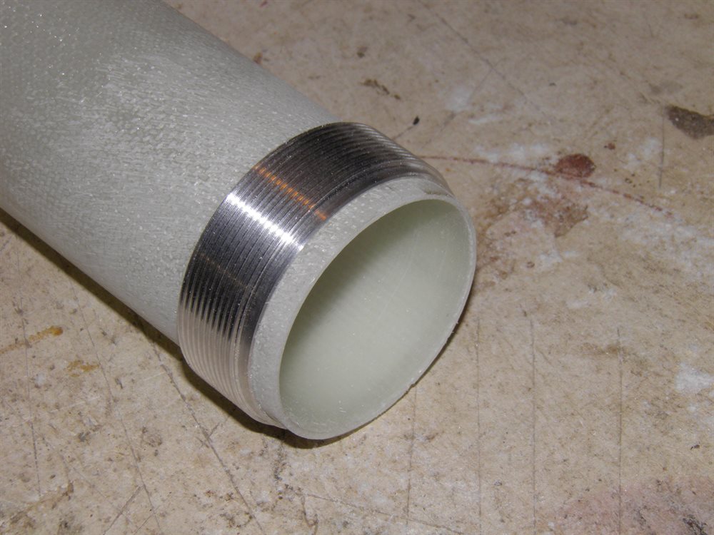
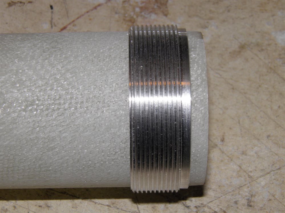
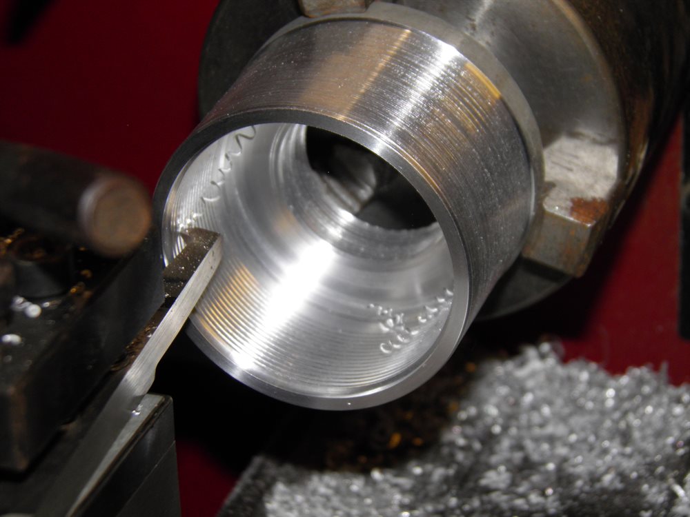
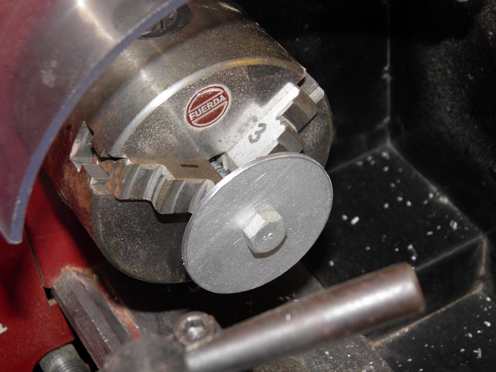
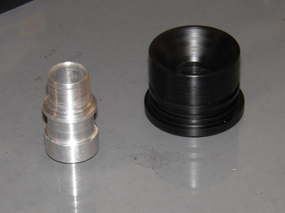
- Over a course of about 3 hours dad machined up the threaded retainer mount and the retainer ring out of a solid chunk of the aluminium bar. We took turns cutting this puppy in half with a hack saw. This was made to fit the fiberglass MMT.
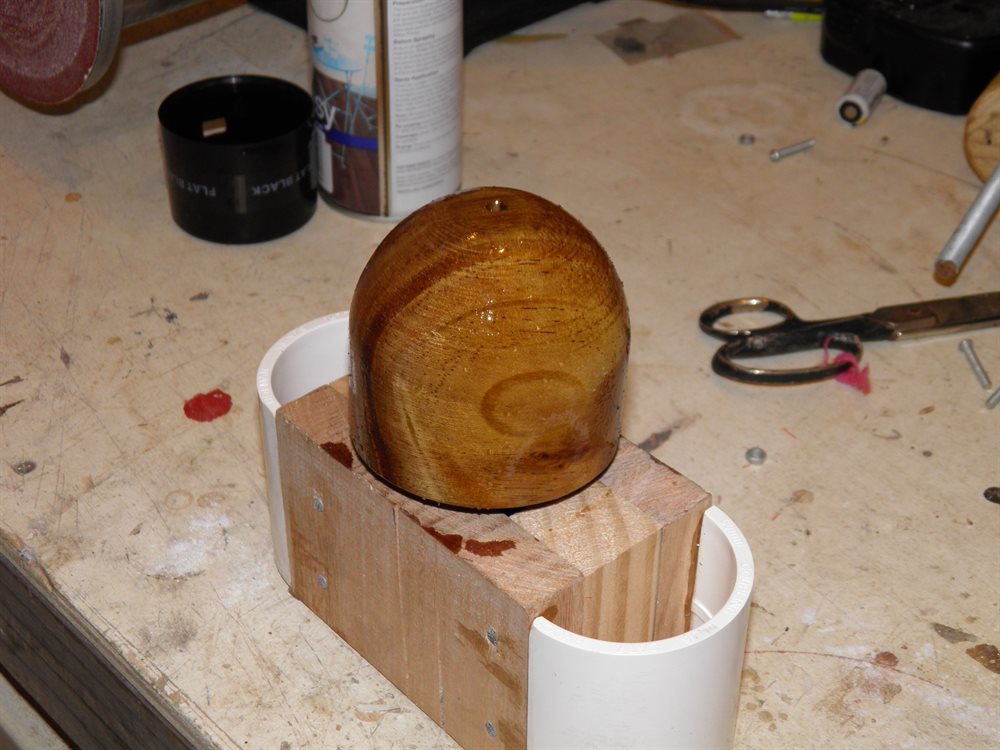
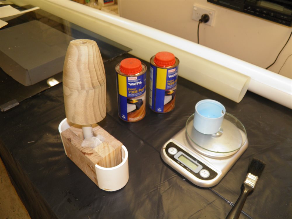
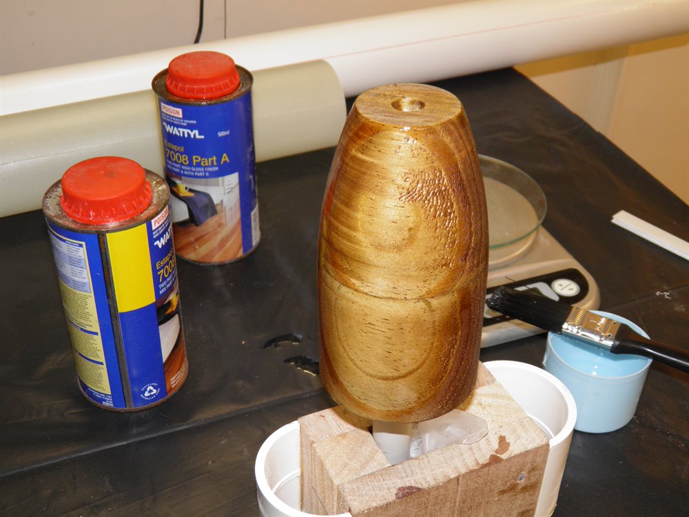
- We painted the top closure plug with 2 pack paint. This should give it a harder wearing surface and seal in the raw wood.
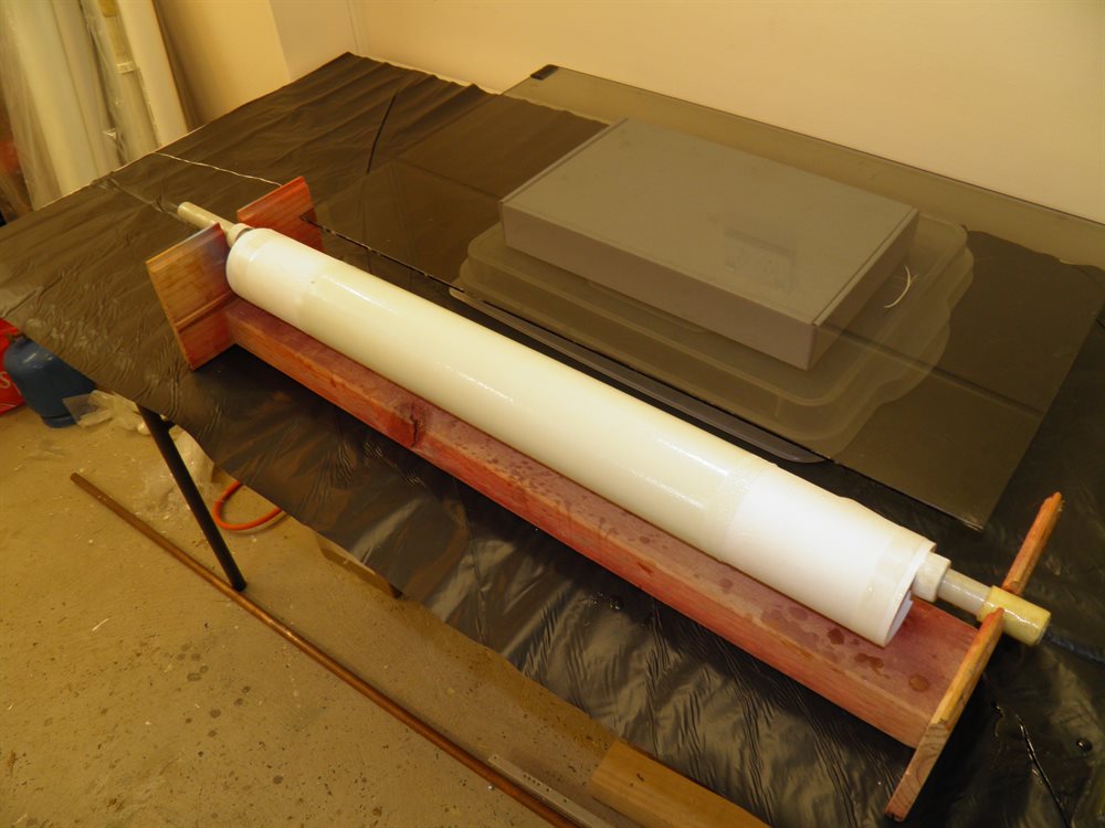
8 August 2016 - We removed the body tube from the mandrel. It came off very easily. We trimmed the ends of the body tube and sanded them. The whole body tube measures 153cm and weighs 667 grams.
We also painted the forward closure plug with a second coat of the 2 pack paint.
We ran an updated simulation in Open Rocket now that we know a little more about the weight of the rocket. It still looks good with a simulated altitude to around 600m on the H.
10 August 2016 - We machined up the nosecone plug today and then painted it with the 2 pack paint. We had to fill in some of the deeper grain bumps with putty.
We also machined up the thrust ring from aluminium that will support the motor. With the motor only producing around 150N peak there isn't a lot of force on it.
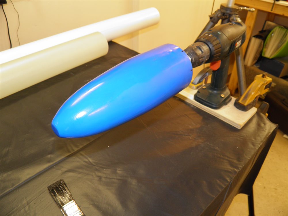
We also prepped the forward closure plug for fiberglassing by polishing it with the mold release wax and then applying a couple of balloons with silicone grease in between.
We also bought the CTI H120 and H125 reloads that will be delivered to one of the club members that has pyro license and he will bring it to the launch site.
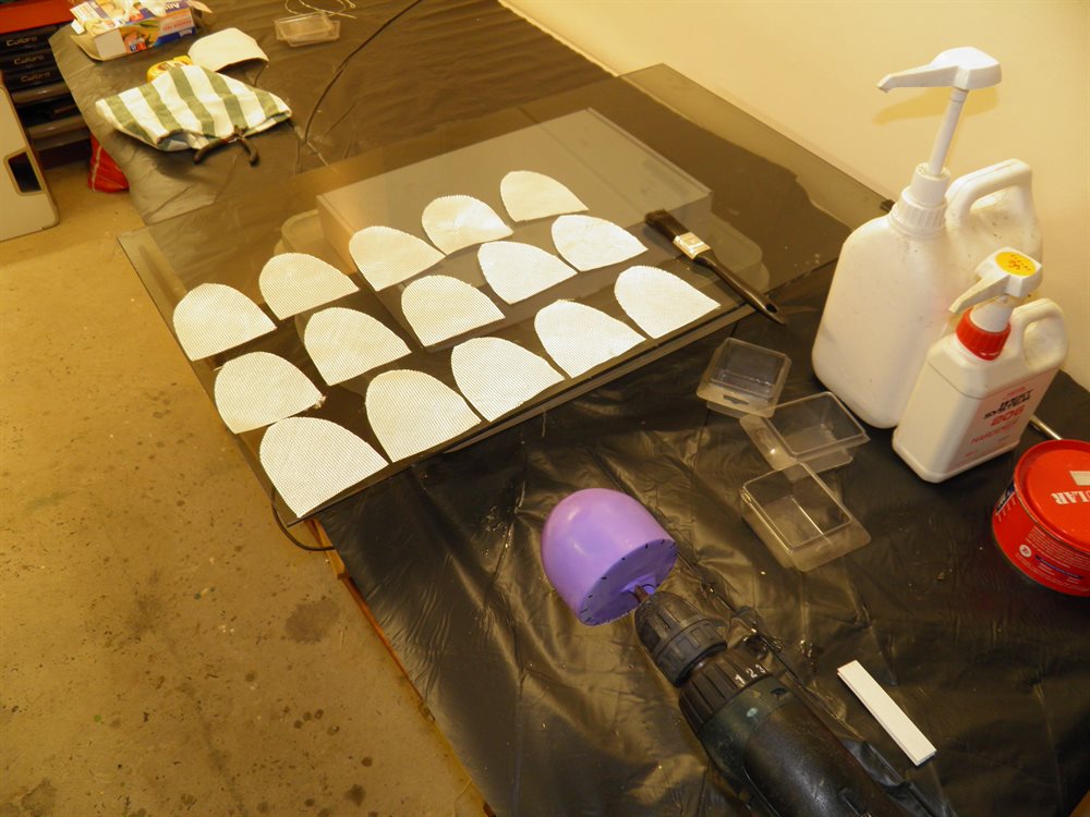
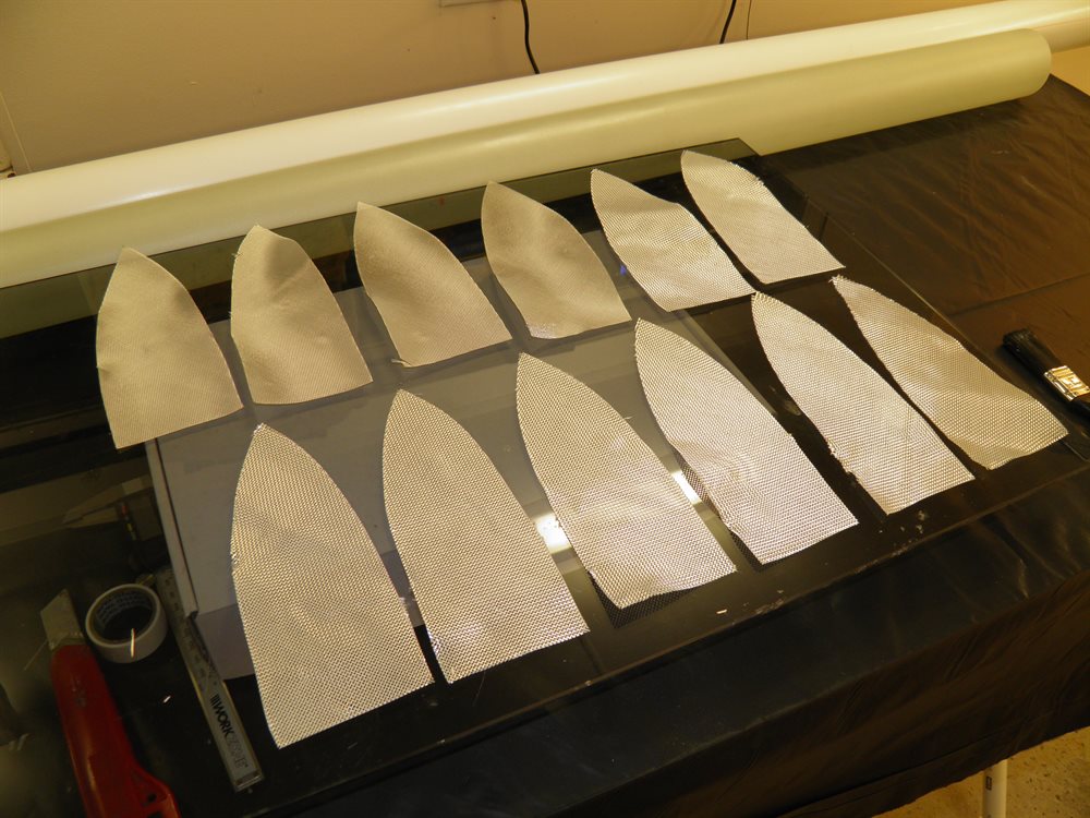
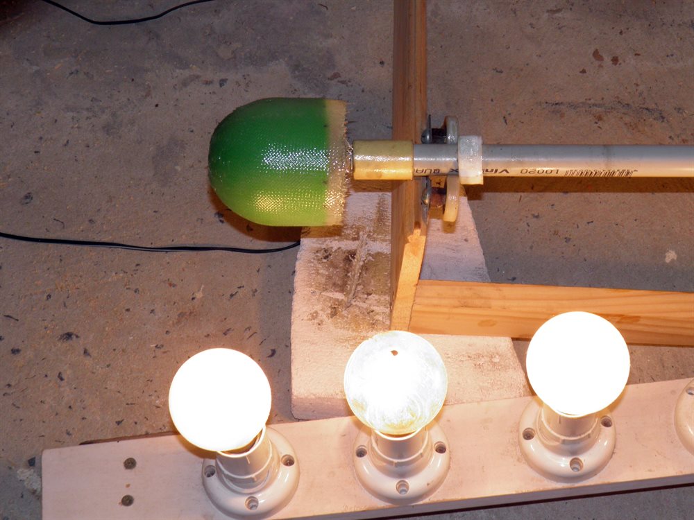
11 August 2016 - Today we made the forward closure with 15 gores of the 200gsm cloth. We also put 3 small layers over the very tip and one 2 cm wide wrap around where base will join to the body tube.
We also applied a second coat to the nosecone plug.


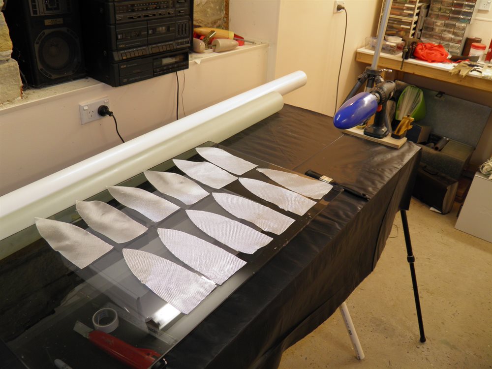
12 August 2016 - We fiberglassed the nosecone today. Since this is not pressurised we used 8 gores of the 200gsm cloth and then 4 veil gores of the 85 gsm cloth for a better finish. One pump of epoxy was used.
We also cut the MMT tube to a 12 cm length.
We removed the forward closure from the plug and test fitted it into the tube. It was a little on the tight side and so we sanded it down. Ideally we would want the plug to be a little smaller perhaps by 0.2mm. We'll see if we'll make up another one that uses less gores and doesn't include the wrap.
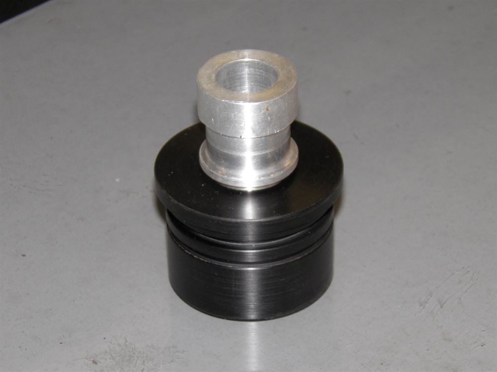
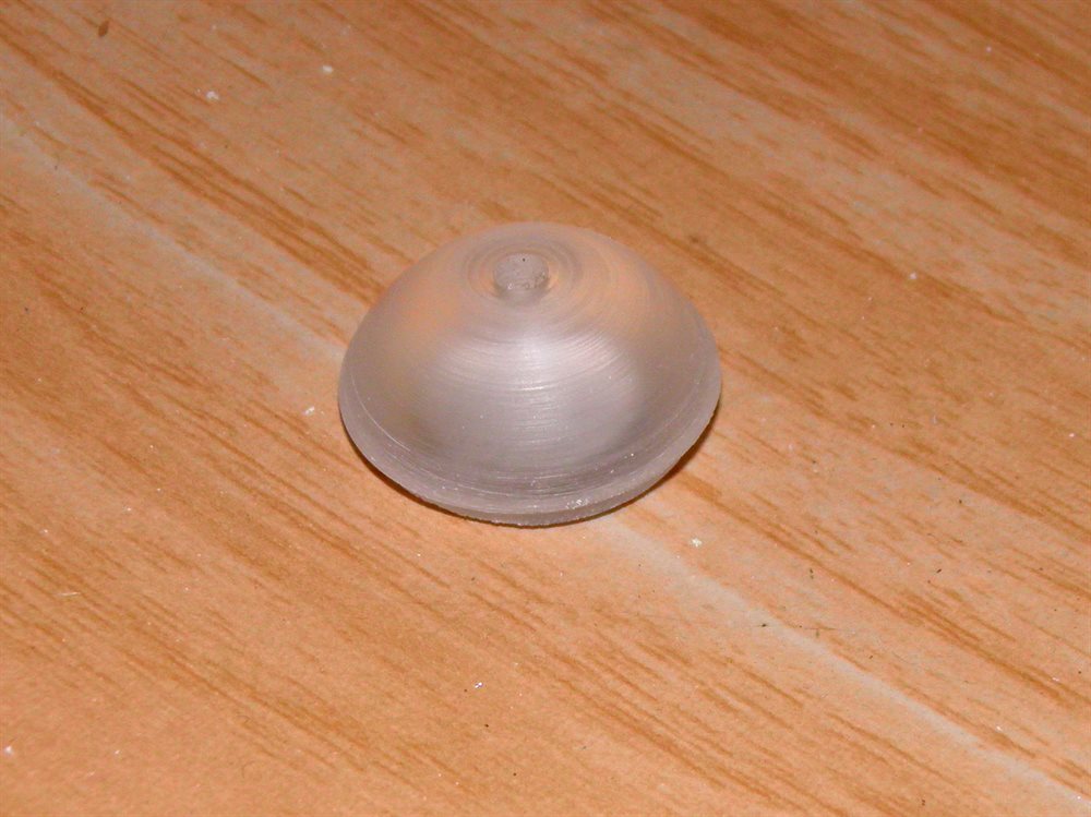
13 August 2016 - Dad machined up the nozzle adaptor today from a piece of plastic. I am not exactly sure what the material as it was an off-cut we had but it machined well.
We also machined up the tailcone plug. The tailcone plug will also be used as an alignment jig when we attach the tailcone to the MMT and so we drilled a 12.7mm hole in the end of it that will allow us to fit a rod that will then align a piece of PVC tubing that was used as a mandrel to make the MMT. We also sanded an coated the plug with the 2 pack paint.
Lastly we removed the nosecone from the plug and trimmed it. It came off fairly easily.


14 August 2016 - We gave the tailcone plug another sand and a second coat today.
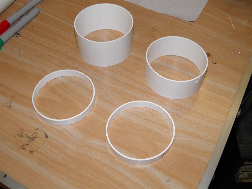
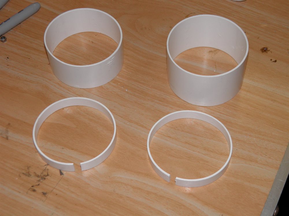
We then cut out two couplers from the PVC pipe that was used as a mandrel for the main body tube. One coupler will be used on the nosecone and the other will be attached to the top of the forward closure to attach the payload bay. Because the wall thickness of this pipe is small we cut out a second ring that was split and will be glued to the inside that will then help support the screws used to attach the payload bay and nosecone.
We also sanded the nosecone and then machined the very tip that will be glued in place with epoxy.
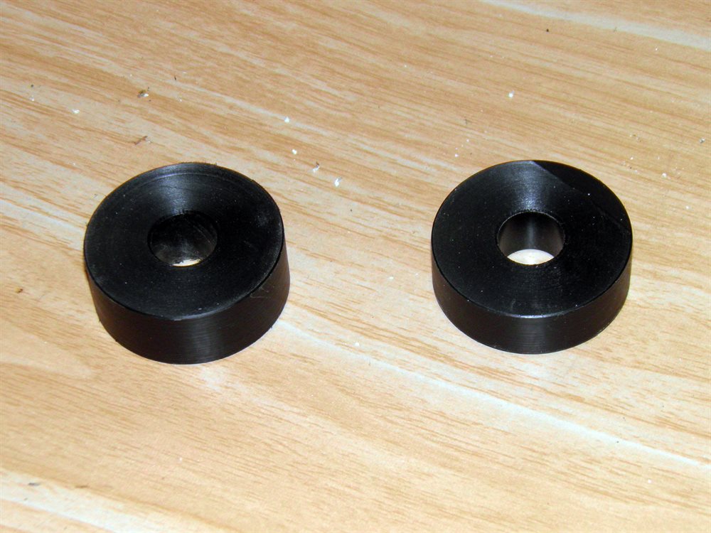
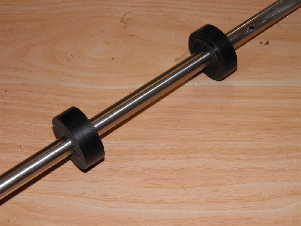
We also machined a couple of plastic centering rings that will fit inside the 40mm PVC pipe (that was used for MMT mandrel) and drilled a 12.7mm hole in them that will support the rod going to the tailcone plug. This will keep everything aligned when we glue the tailcone to the MMT.

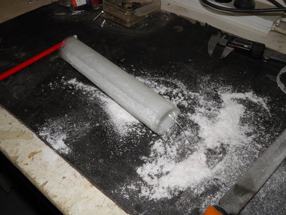
15 August 2016 - Today we fiberglassed the tailcone with 14 gores of 200gsm cloth. We did not use a wrap layer this time. We used 1 pump of the epoxy. We also made a smaller fiberglass tube that may be used as the central core of the deployment mechanism.


16 August 2016 - We removed the tail cone from the plug and then sanded it.
The central tube was also removed from the mandrel and trimmed.


18 August 2016 - We sanded the forward closure and tailcone today to allow it to smoothly slide into the body tube.
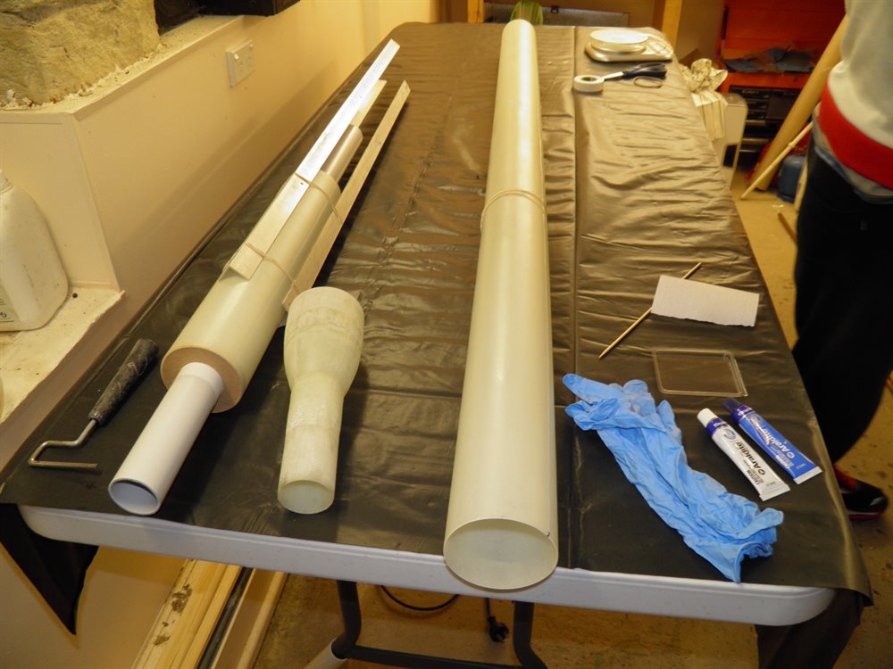
19 August 2016 - We made a rotisserie adaptor out of a PVC pipe and a couple of cardboard centering rings. This would allow us to connect the open end of the body tube to the motor and allow us to rotate the tube while the forward closure cured. We hadn't used this technique before when gluing end closures and it worked well to stop drips from forming on the inside.
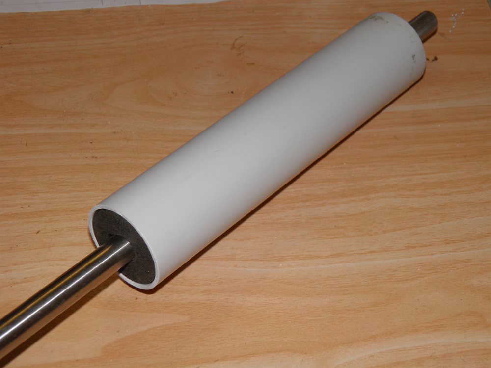
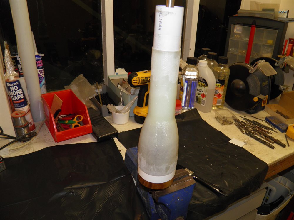
We attached the tail cone to the MMT. To keep it all aligned we used the tailcone plug to hold the tail cone, and then we inserted the 12.7mm pipe with centering rings into the top of that. We then put a piece of the 40mm PVC pipe over the top of that and threaded it through the tailcone end. We offset the tailcone a little bit from the plug so that the joint was free of the plug otherwise it may have glued itself to it. We wrapped the PVC pipe with one wrap of baking paper to make sure it also did not stick. We then slipped the MMT over the top of that and joined the two sections together by using a number of 200gsm gores, and finally adding another 4 85gsm veil gores over the top for a better finish.
The nosecone tip was also epoxied into the nosecone.


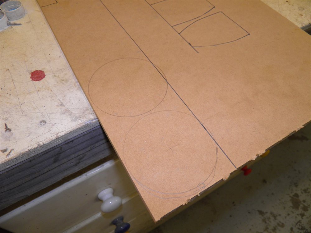
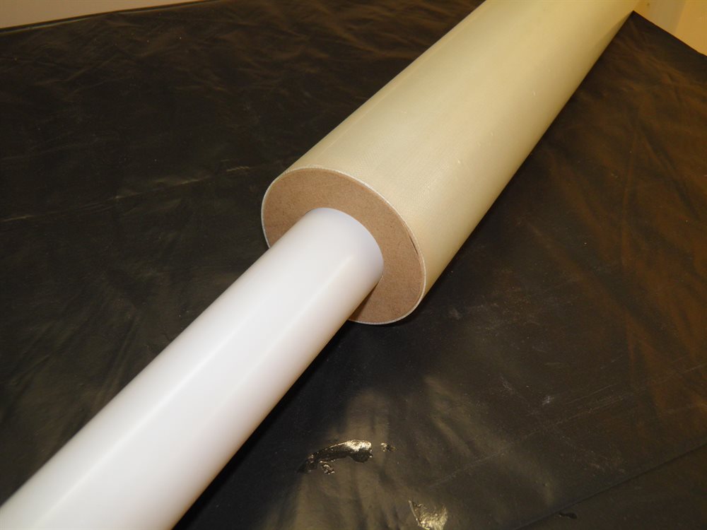
20 August 2016 - We machined up a couple of 80mm centering rings from 10mm MDF. These were going to be used to hold the 40mm pipe inside the 80mm tube. This made up a MMT alignment jig to ensure that when we glued the tailcone into the end of the body tube they would be perfectly aligned.
We epoxied the tailcone into place with the 24hr epoxy inserted the jig
and put 3 angle brackets between the jig and the body tube to keep
everything lined up. We then added a number of rubber bands over all of them
to keep everything together.