| Date: | 29th October 2016 |
| Location: | Whalan Reserve, Australia |
| Conditions: | Overcast first, then sunny, light breeze, 22C |
| Members: | PK, Paul K and GK |
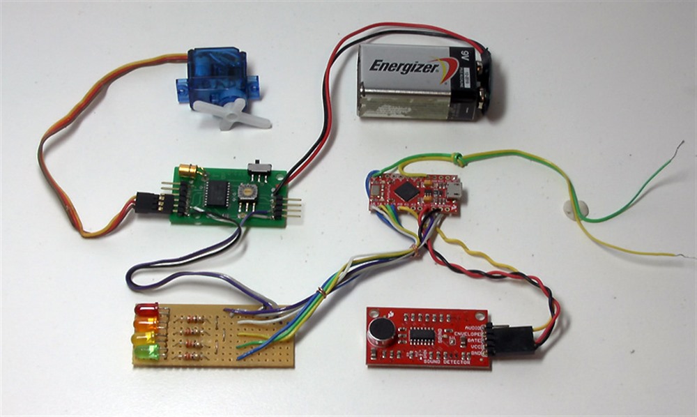
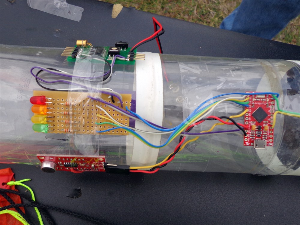
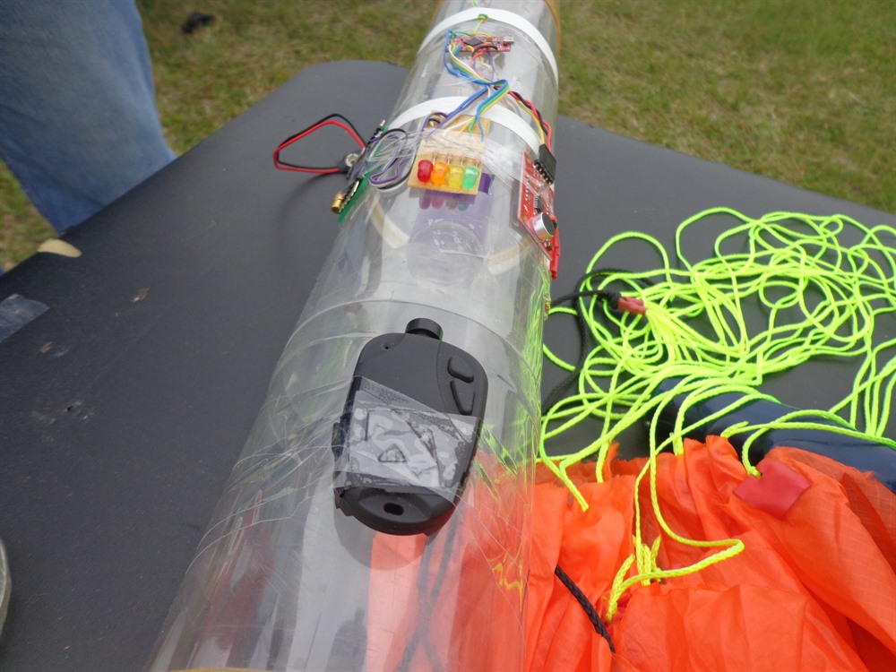
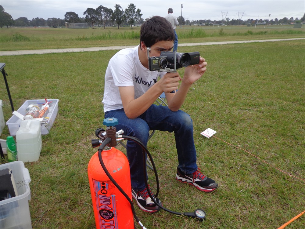
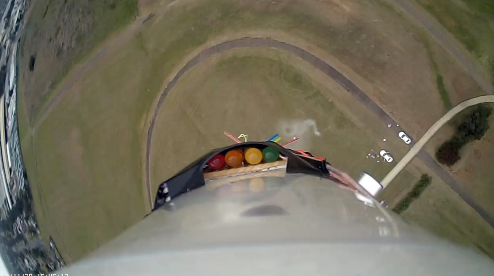
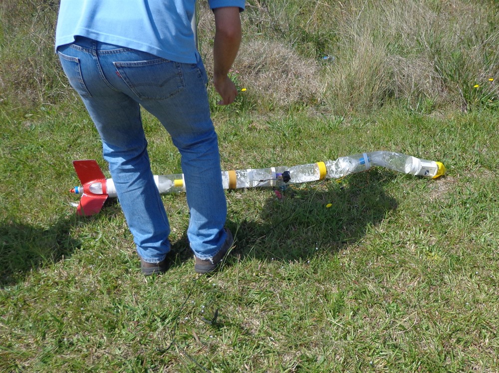
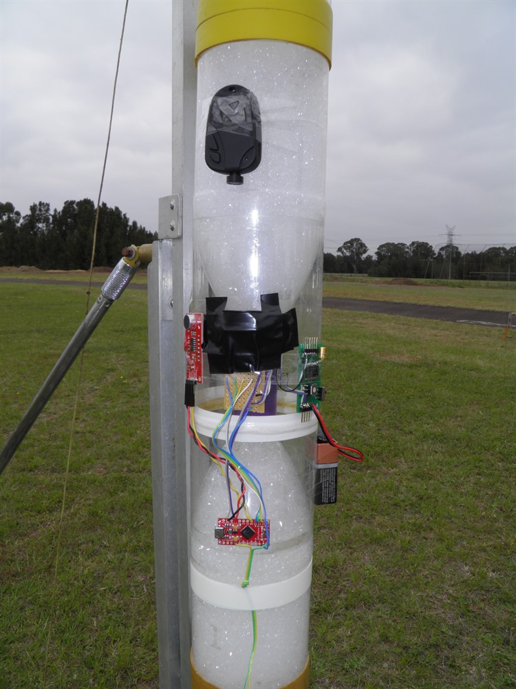
This is a continuation of the initial tests done back on day 178. Since then we have wired up the rest of the circuit as originally intended and written the basic code to get it all to work. We had finished soldering up the experiment the night before launch as basically a birds nest of controllers and then just taped these to the side of the rocket. We connected a set of 4 LEDs to give us a status readout of what the circuit was doing, We then attached a camera above the LEDs looking down so that we could see what the circuit was doing in relation to the rest of the flight.
The final circuit we used for the Acoustic Apogee Detector consists of a Pro Micro 5V 16Mhz micro-controller from SparkFun. This is directly wired to the Sound Detector and outputs the trigger to the Servo Timer II that controls the deployment servo. We could have wired up the servo motor directly to one of the available pins on the Pro Micro and then written extra code to deal with configuring and activating the servo but it was just easier to get it to send a trigger signal to the STII. The STII also provides a stable 5V power supply for the rest of the circuit.
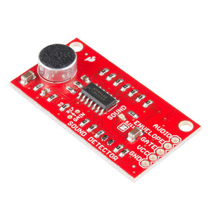

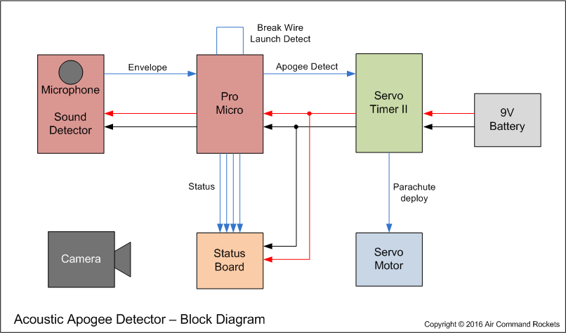
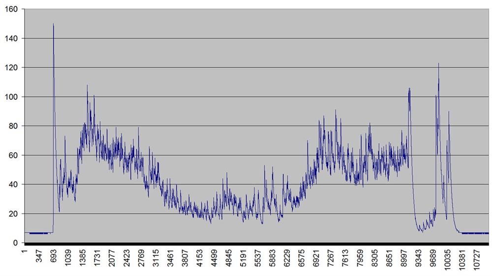
The Sound Detector amplifies the sound from the microphone and produces an analog envelope waveform. The envelope is basically the volume of the sound entering the microphone. We used a 22K resistor on the Sound Detector to set an amplification gain of 18dB. The envelope signal is then fed into one of the Pro Micro's analog inputs. The controller then samples this envelope at 100Hz and averages these every 0.1 seconds to give us a reading at 10Hz.
The controller when turned on, enters a wait-for-launch state where it ignores all sounds while it sits on the pad. A break-wire launch detect input to the micro-controller starts it listening to the sound level. If the controller senses 5 consecutive readings with values higher than the previous then it senses acceleration. It changes state and then starts listening for 5 consecutive decreasing readings indicating deceleration. When it detects deceleration it then switches state again and starts listening to acceleration once more with the same criteria. When the second acceleration is sensed the controller sends a trigger signal to the Servo Timer II that then activates the deployment Servo Motor. The Servo Timer II's delay is set to 0 seconds.
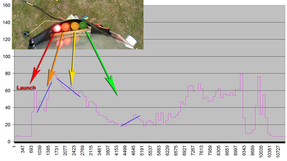
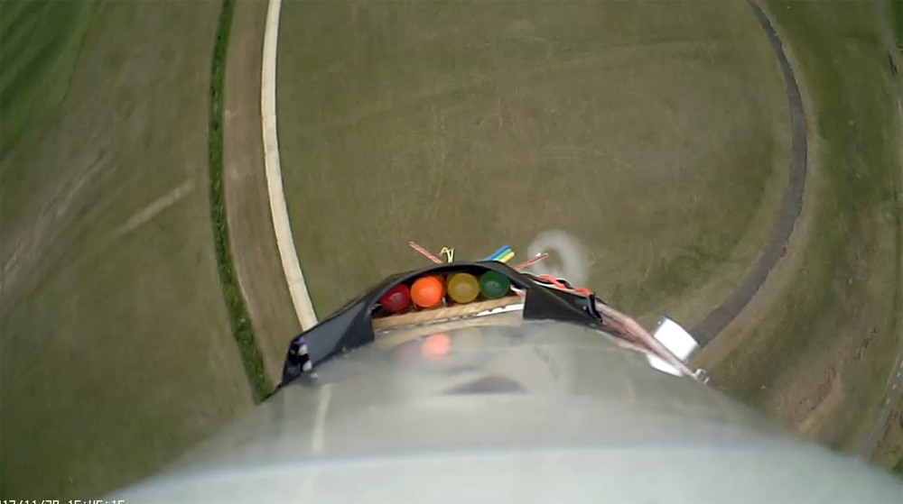
The controller also has 4 status LEDs connected that are recorded by the on-board camera during flight. When all 4 LEDs are on, the circuit is waiting for launch. The red LED represents launch detected, the orange one represents acceleration detected, followed by yellow indicating deceleration, and finally the green LED indicating deploy.

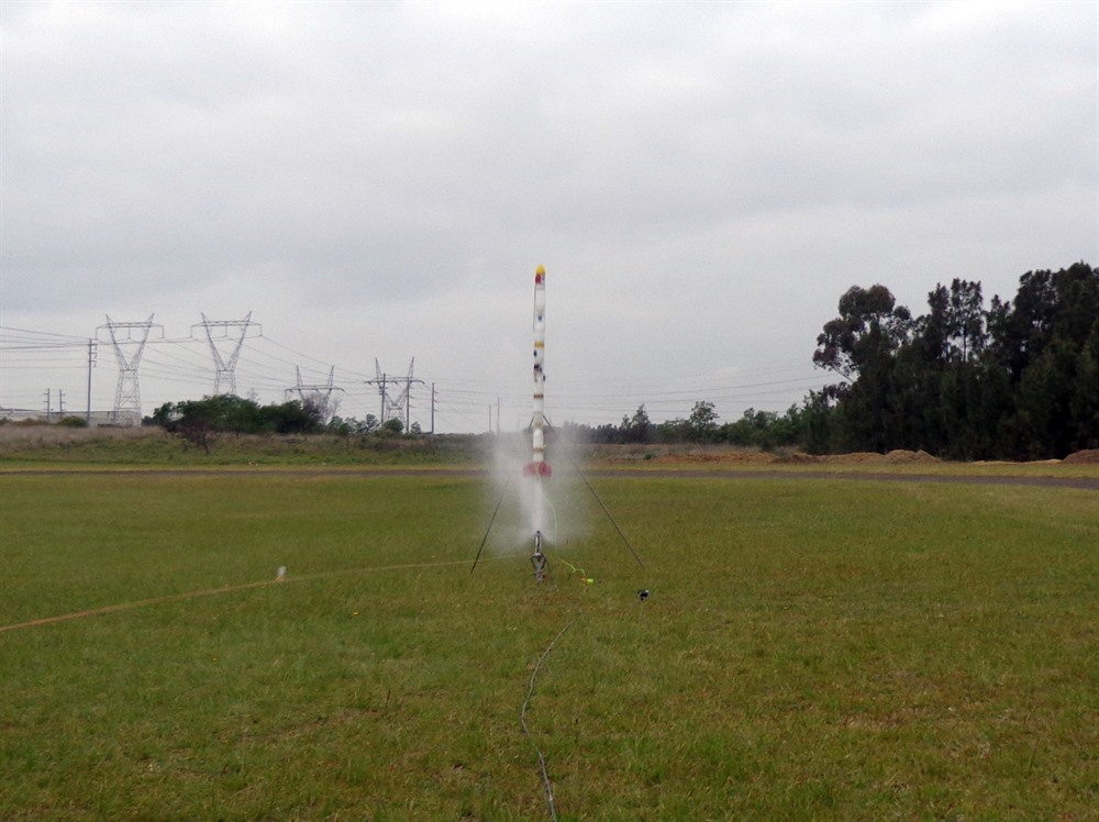
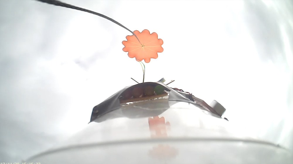
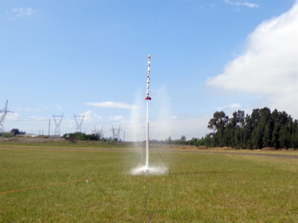
On the first flight we ran the whole experiment with the exception of the deployment servo being connected. That was still controlled by the timer in the nosecone. We wanted to see if the status LEDs would show that the system was working. The timer delay was set a little after apogee so that the air speed could increase past the rocket allowing the experiment to sense the acceleration after apogee. The rocket was pressurised to 120psi and launched. The parachute deployed a little after apogee and the rocket landed safely.
Reviewing the video it showed that the deploy LED lit when it was supposed to so we decided to try it for real on the next flight.


We disconnected the deployment servo motor from the regular timer and hooked it up to the STII in the experiment. The rocket was again pressurised to 120psi and launched. The rocket went up as normal and then a few moments after apogee the parachute deployed. The system had worked as expected. :)
The same results were obtained with flight 3 with the parachute again opening a little after apogee. The rocket landed safely in both cases.

We set the rocket up again in the same configuration as flights 2 and 3 and launched it. The rocket went up and came straight back down and nicely bounced when it hit the ground. The top half of the rocket was buckled, but all the electronics survived without issue.
Reviewing the video showed that launch, acceleration and deceleration all were detected, but the post apogee acceleration was not detected. Since we weren't logging the actual data coming from the Pro Micro we don't know why it didn't detect it, but most likely 5 consecutive samples did not meet the accelerating criteria.
In hindsight we probably should have had like a 9 second backup timer just in case apogee was not detected. Oh well, we have some more Coke to drink to replace the damaged bottles.

The first 3 flights showed that the circuit worked as well as expected with the detection parameters chosen (sample rate, number of sample points, amplifier gain, detection conditions). Flight 4 showed that the system has its limitations with the simple algorithm running on the controller. A more sophisticated algorithm should be able to detect apogee a lot more reliably.
Realistically you wouldn't use this kind of apogee detector in practice as barometric and acceleration based sensors are much more accurate at detecting apogee. Still it was a fun experiment to try to see if we could get it to work.
| Launch | Details | ||||||||||||||||||||||||
| 1 |
|
||||||||||||||||||||||||
| 2 |
|
||||||||||||||||||||||||
| 3 |
|
||||||||||||||||||||||||
| 4 |
|
||||||||||||||||||||||||
| 5 |
|
||||||||||||||||||||||||
| 6 |
|