These tutorials show you how to build some of the components
we use on our rockets. While it may not always be possible to
reproduce these components exactly, many of the designs can be
customized based on the materials you have available.
For a full list of all construction tutorials go to the
Construction Index.
Gardena Launcher
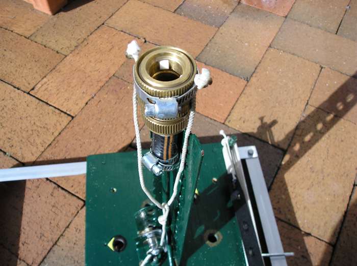
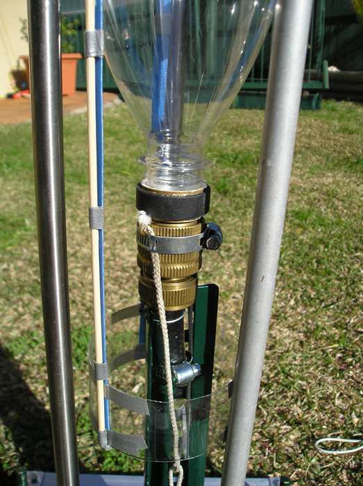
Release mechanism detail. with attached
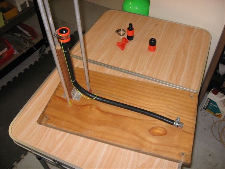
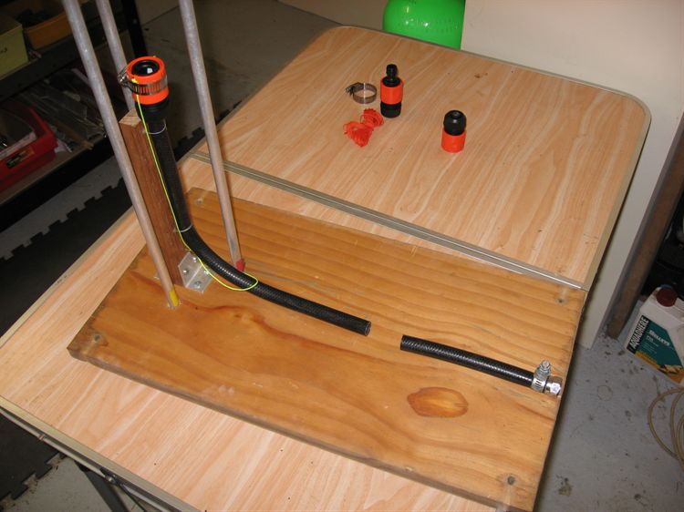
string.
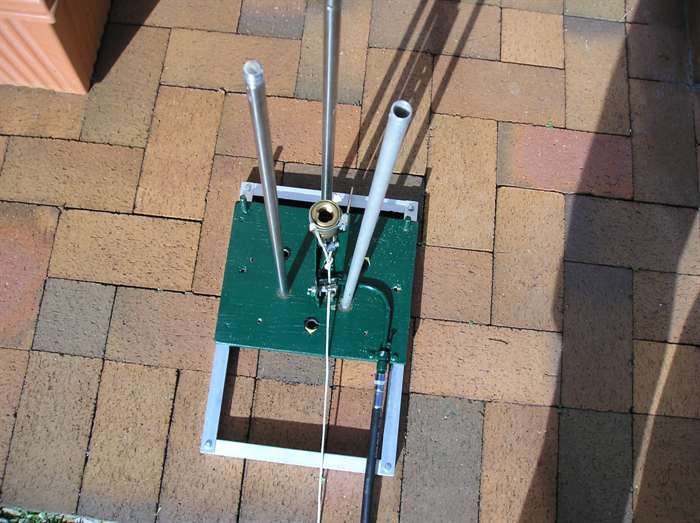
Rocket guides in place.
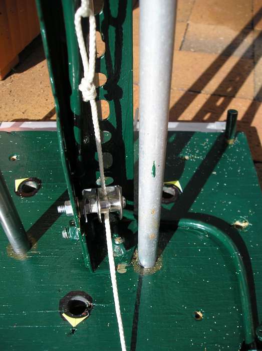
Release string pulley at the bottom of the
release mechanism.
A rocket sitting on the launcher in launch
position.
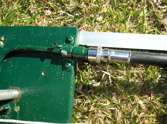
A quick release hose connection for the air
supply.
The release string is neatly stored for
transport.
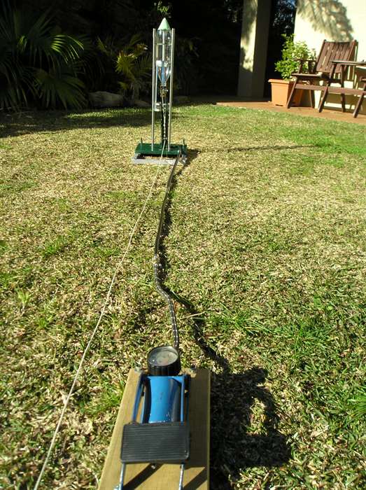
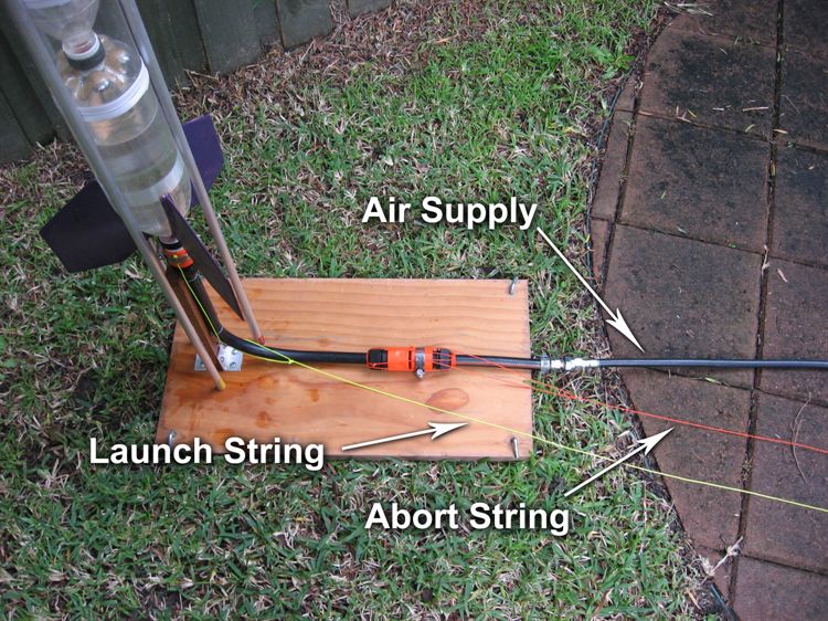
A typical launch setup with air supply and
release string.
Launcher and rocket.
The launcher consists of a stable base with a vertically
mounted release mechanism. The launcher also provides a guide
for the rocket during take off. This helps to steer it in the
right direction before the fins can take effect.
Procedure
Base
First we start with the base. Cut a square or
rectangular piece of wood as shown in the photo. Don't worry
about exact dimensions as it does not matter. If it is too
small the launch pad will tip over, but if it is too big it
becomes cumbersome to carry and transport. Make sure the
wood is not chipboard or MDF as it will get soaked quite a
bit. Marine plywood is usually the best choice. The wood
should be fairly thick to provide enough support for the
guides.
Attach an aluminium frame to the base. This helps
keep the launcher from tipping over. Again exact
dimensions are not important.
Find the center of the board and draw two concentric
circles, one at 95mm and one at 115mm. These will represent
the two most common bottle diameters 1.25L and 2L
respectively. If you are using different size bottles
measure the diameter and add ~5mm for clearance.
Divide each circle into thirds and mark the locations on
the board. This is where the vertical guides will be placed.
Find wooden dowel or aluminium tube of around 10-12mm in
diameter and cut into 3 equal lengths. These will become the
rocket guides. The length of these will depend on the
release mechanism height. The guides need to be long enough
to guide the rocket during the first part of the launch.
Exact length is again up to you.
Drill vertical holes at the markings on the board such
that the guides do not overlap the circle. Make sure that
these holes are a snug fit when you insert the guide. This
is best done with a drill press rather than a hand drill.
Repeat the drilling for the other circle(s) spacing the
holes around the circumference.
This guide design was chosen because it allows for both
ring fins, and the more conventional flat fins.
Release mechanism
The release mechanism is consists of a garden hose
fitting attached to an air hose. We have used a brass
fitting because it was of reasonable quality and had a
smooth pullback action. Be careful when using cheaper
plastic fittings as these may not seal as well and may
prematurely release the rocket at higher pressures.
Attach an angle bracket vertically to the center of
the base. This should be long enough to enable a rocket
to sit on top and still have enough clearance for the
fins.
Attach a length of garden hose to the garden hose
fitting, and then attach the air hose directly to the
garden hose. Use of hose clamps and adapters is
encouraged. The air hose attachment method will depend
on what you have available and what your air supply has
as its output. Try to keep the number of transitions to
a minium in order to minimise potential sources of air
leaks. We used a quick release adapter at the base to
make it easier to pack up and transport.
It is a good idea to put a non-return valve in line with
the air hose to prevent water from going back into the
air supply. We built a custom non-return valve into the hose
fitting, but others have used bicycle tyre valves or
other forms of valves. If you cannot get your hands on a
valve, it should be possible to just create a loop in
the air hose whose apex is above the the
rocket's fill waterline. Kind of the S-bend principle of
a toilet (where the air is pumped in from the sewer
end). I highly suggest you don't use a toilet as your
non-return valve.
Attach the hose and/or the base of the hose fitting
securely to the vertical angle bracket using hose
clamps, or cable ties. Ensure that the centerline of the
hose fitting is inline with the centerline of the
concentric circles on the base.
Using another hose clamp attach either side of a
piece of string to the movable part of the hose fitting.
To this string attach a long piece of string that will
be your launch string. Create a hole in the bottom of
the vertical angle bracket to feed the release string
through. If the edges are too rough you could set up a
pulley system as we have done, to stop the string being
cut. The idea is to turn the horizontal pulling action
into a vertical one to pull down the hose fitting.
You can hammer in a couple of nails in the base
board that will allow you to wrap the string around for
tangle free transportation.
We painted the board with water proof paint to help
stop the wood from absorbing too much ... you guessed
it ...water.
Air supply
Your choice of air supply will depend on what you
have available and are comfortable using. A bicycle pump
is cheap and easy to use, but requires a lot of work. A
car foot pump is easier but still requires a bit of
work.
We prefer to use a small 12V compressor intended for
filling car tyres. Ours goes up to around 120psi. We use
a small 12V 7.5Ah sealed lead-acid (SLA) battery to
power the compressor. Both are easy to transport and a
battery charge will last you all day. The typical fill
time for a small 2L rocket is around 40seconds - 1 min.
For
higher pressures you can use more expensive compressors,
but for really high pressures you can use a SCUBA tank
with an adjustable regulator. We prefer to use a SCUBA tank
on the larger rockets, but it is a little cumbersome to carry
around.
Many different designs for launchers are
available on the internet so make use of your favourite
search engine.
The purpose of this tutorial is to build a
simple remotely operated pressure release valve out of common materials
requiring no special
tools.
Background
An abort valve is a very important safety feature of a
launcher. On
occasions you will encounter a situation where an already
pressurised rocket needs to be prevented from leaving the pad
and pressure in the rocket needs to be released. Some reasons for aborting a
launch include:
The recovery system malfunctions or accidentally
deploys while the rocket is still on the pad.
The range may become unsafe such as when people,
vehicles or animals enter the range.
A slow leak may develop that might lead to a
catastrophic failure if pressure is not released quickly.
While a pressure release valve could be located close to the
air source, a problem exists if the launcher needs to use a non-return valve (check valve)
to keep the water from flowing back into the air line. In this
case the non-return valve should be located as close to the
rocket as possible. In order to release pressure from the rocket
the pressure release valve needs to be located on the rocket
side of the non-return valve. Having a manual pressure release
valve next to the rocket means a person would need to operate it
while standing next to the pressurised rocket. A remotely
operated valve is required for safety.
You may want to prevent water from going back down the air line
for two main reasons:
Keep as much of the water in the rocket as possible.
The water may damage your pump if it is designed only for
air.
If your launcher uses a launch tube that only allows air into
the rocket above the water line you may not need the non-return
valve, however, it is still a good idea to have one in order to
prevent water escaping down the launch tube and into the air hose while
loading the rocket onto the pad. And when the rocket takes off
water is forced down the tube.
It
should be possible to attach this mechanism to the air line of most
existing launchers if they're not already fitted with
non-return valves. In the procedure below we integrate a simple
non-return valve into the pressure release valve.
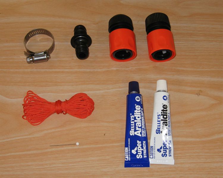
Materials Needed
2 x Gardena quick connectors
Gardena extension adaptor
Hose clamp
Epoxy glue
Sewing pin with a round head
Nylon String
Tools needed
Scissors
Drill
Screwdriver
Sandpaper
Pliers
Bluetac / plasticine / modelling clay
Procedure
If you are going to fit this mechanism to a launcher that
does not require a non-return valve then you can
skip steps 1 - 7.
Non Return Valve
1.
Sand the internal hole of the Gardena quick connector.
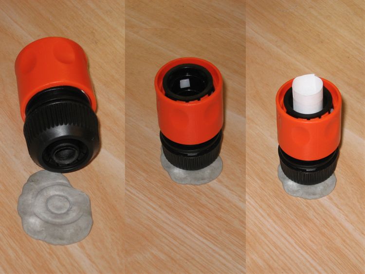
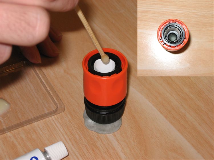
2.
Put a piece of Blu-Tack, plasticine or
modelling clay on the workbench and stand the
Gardena connector on it's end (orange collar pointing up) so
that the Blu-Tack blocks the central hole. You may want to
make a protective cylinder from a piece of paper so that
you don't get glue on the inside walls near the top of
the coupling.
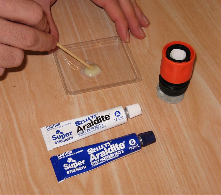
3.
Mix up some epoxy and carefully pour it through the open
end. Pour enough epoxy
in so that it is about 1cm deep.
4.
Let the epoxy fully cure for at least
24 hours. It is better to use the
longer cure but stronger epoxy than the 5
minute stuff.
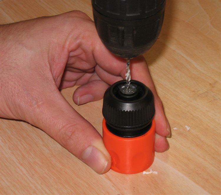
5.
When the epoxy has cured, drill a small hole through the
center of the epoxy. The hole should be smaller than the
head of the pin. Usually about 1.5 - 2mm is good.
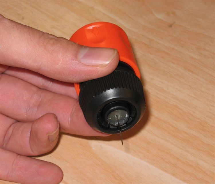
6.
Insert the pin so that the head is on the inside of the
coupling. With the sharp end pointing out of the hole.
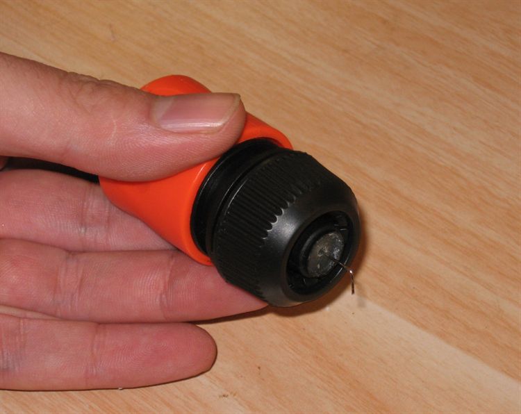
7.
Cut the sharp point off and bend the end of the pin 90
degrees. The bent section should be about 3 mm and there
needs to be about 5mm movement of the pin. This is the
non-return valve.
Pressure Release Valve
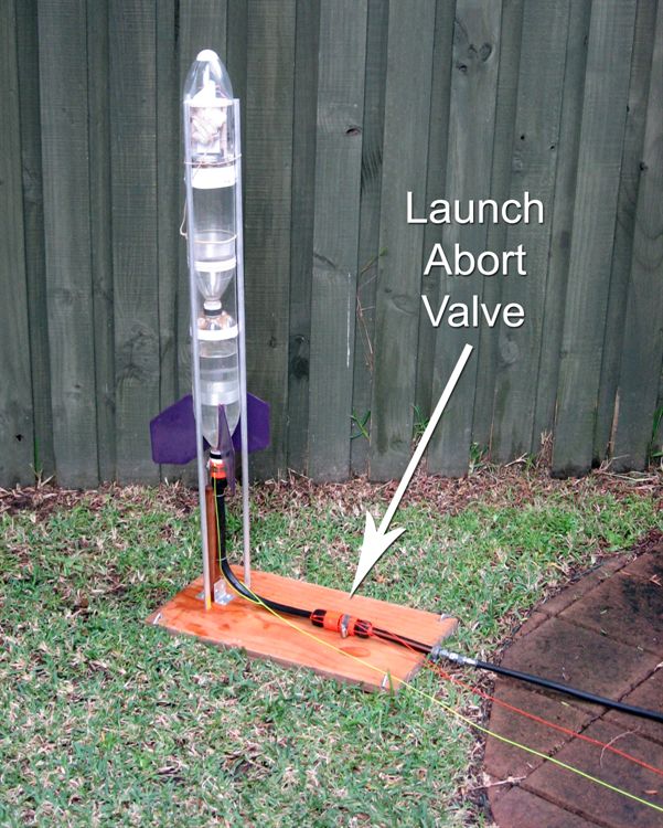
8.
For illustration we show the launch
abort valve fitted to a simple Gardena launcher.
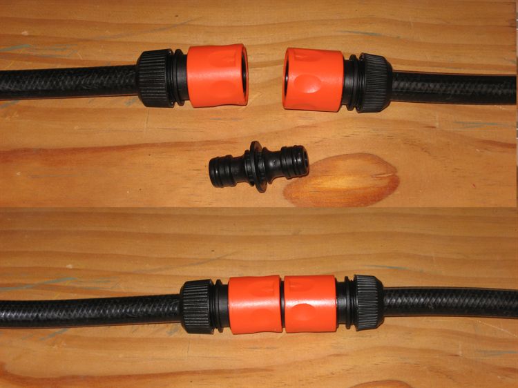
9.
Here we cut the garden hose air line
where we want to fit the abort valve.
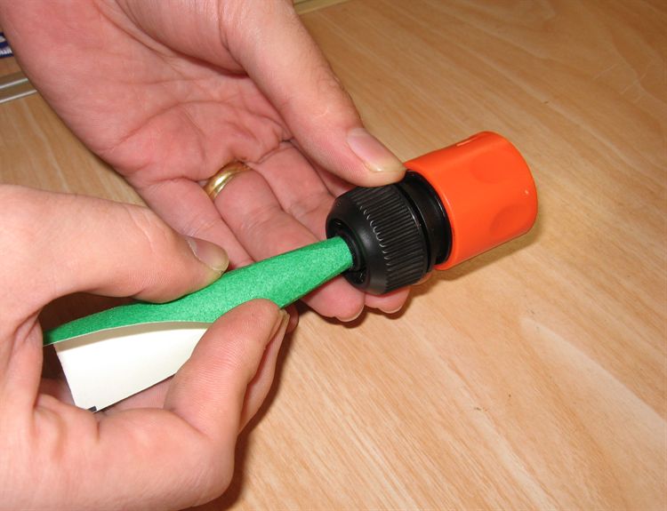
10.
Insert the two hoses into the respective couplings
making sure that the one with the non-return valve is closer
to the air source. Tighten the coupling nuts to secure the
hoses. Snap the extension adaptor into the hoses to check to
make sure everything fits.
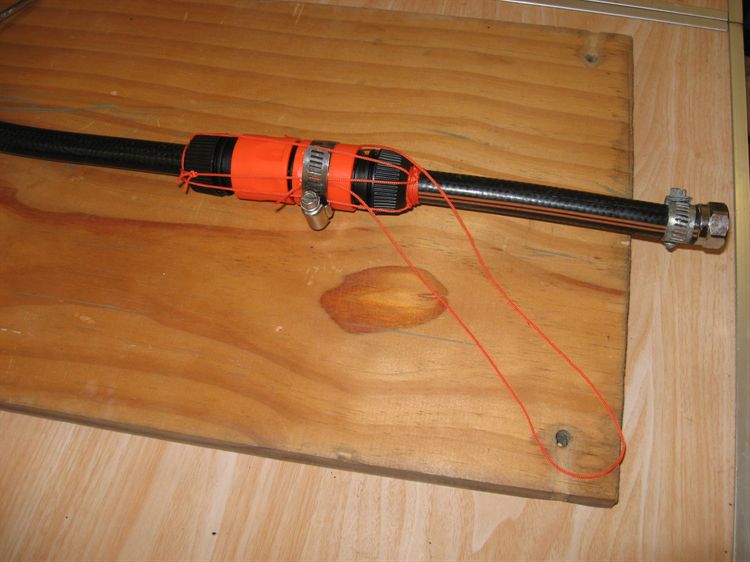
11.
Put a hose clamp around the coupling
with the non-return valve and pinch two ends of loop
made from a short length of string under it.
Tie a string around the hose near the base of the
coupling and run it to the other hose near the base of the
other coupling and tie it off. Do this three or four times
around the couplings. Make sure that there is enough slack
in the lines to allow about 2 cm of movement.
12.
The pressure release valve is now complete. You will
want to attach the hose near the rocket to the launcher so
that it does not move when you pull on the abort string.
Connect a long string to the short loop on the valve.
Make the string as long as your launch string. It is a
good idea to make it a different colour so that you
don't accidentally pull the wrong one.
NOTES:
If you use an air hose that is a different diameter to
the garden hose used in this example, you
can use a short lengths of garden hose connected to the couplings, and make hose adapters for your
specific air
hose. There are many adaptors available on-line or from your
local hardware store. Here some examples:
You can also easily insert a inner tube (Schrader) valve into the
end of the hose and use a small hose clamp to secure it in
place. Be aware that these don't work as non-return valves
when the air hose is connected to them.
You should be able to use brass Gardena couplings or
similar quick connect fittings if
you wish to use higher pressures, but make sure
that any connected hoses are also rated for the appropriate pressures.
To reset the valve simply click the couplings back
together.
The simple 'pin' non-return valve is less than ideal, but for the
most part it should seal well.
You may find a Gardena quick connector that already has
a non-return valve built in. These are unsuitable as the
valve only operates when nothing is snapped into the
connector.