For Dark Shadow we wanted to make a
lighter deployment mechanism than what
Shadow used. One way to make it lighter was
to reduce the overall length meaning there
was less fiberglass in the body tube. This
also meant ditching the piston mechanism and so
we went with rubber bands to eject the
parachute. For the expected high
accelerations we again avoided going with a
side deployment and went with the
in-line approach.
Here is a video that describes the
design and operation of the deployment
mechanism
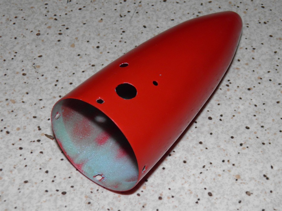
Nosecone
In order to make the deployment mechanism
as compact as possible we wanted to use up
as much of the internal space as possible.
So since the nosecone was mostly empty we put
the camera in it. This allowed us to
reduce the overall length of the payload bay
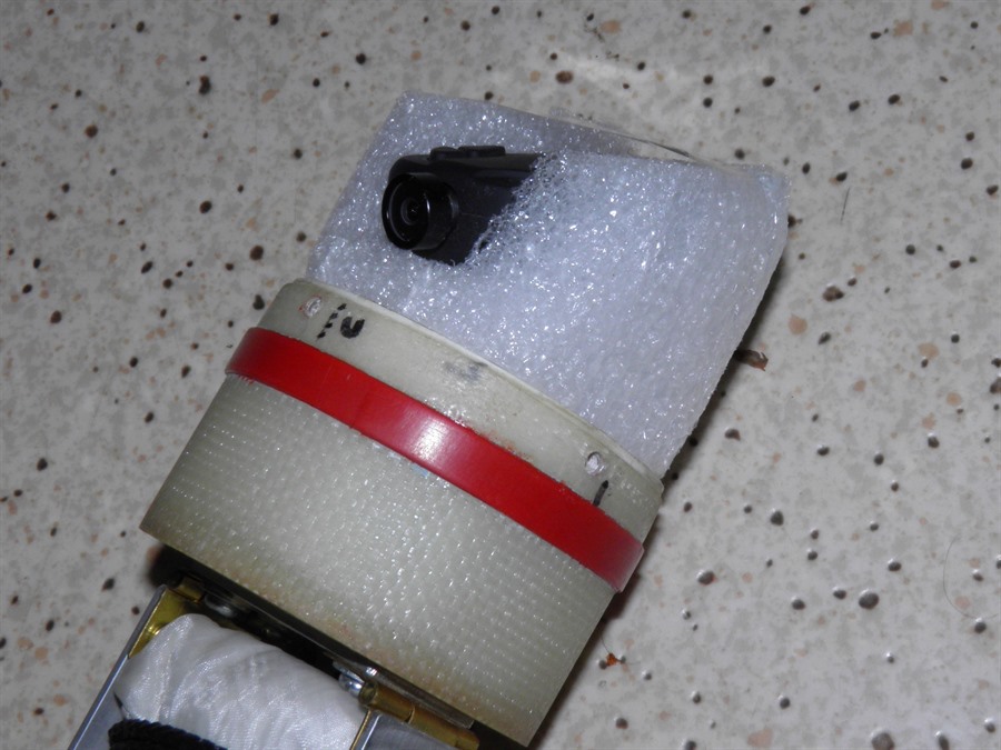
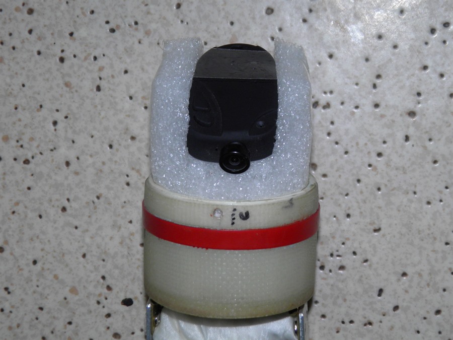
even further. The nosecone shell is removable to allow
access to the 808 #16 V3 camera. The camera is just
held in place with a foam block with a piece
of tape over the top. The camera lens
partially pokes out through the shell for
minimum drag and clear view. A pair of access holes allows
us to operate the camera with the nosecone
shell
assembled.
Camera is housed in a foam
block.
Tape pulls foam sides together
to
grip the camera
Nosecone shell
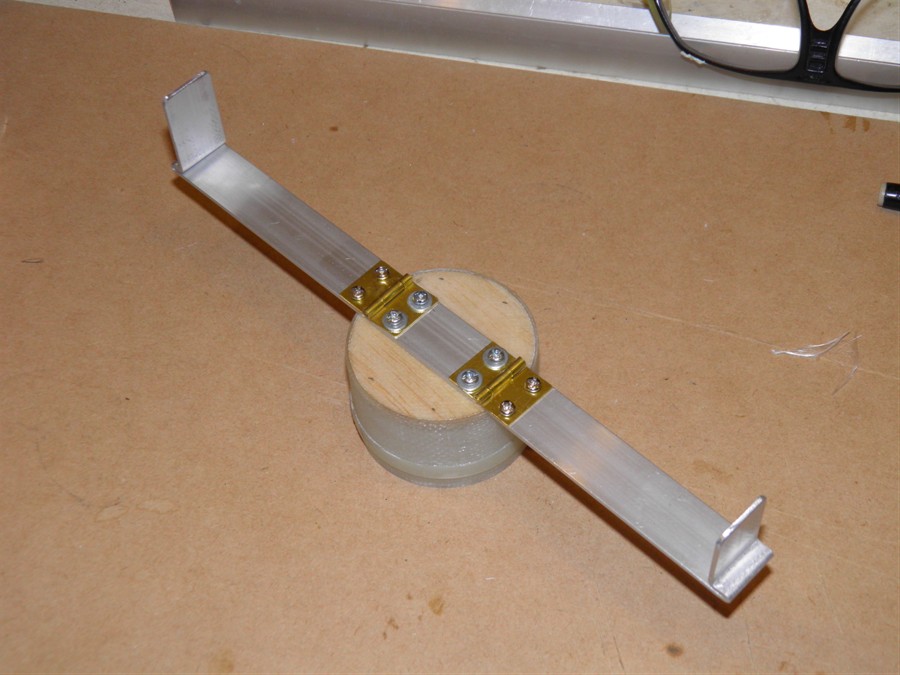
Grapple Arms
The grapple arms serve two purposes. They
provide something for the rubber bands to
pull against while pushing the
nosecone out of the body tube. They also
help pull the parachute out of the payload
bay. The grapple arms are hinged so that when
the nosecone is ejected they are free to
swing open and let the parachute fall out
from between them. The parachute fits just between the
grapple arms so that when inside the
body tube they can't open outwards and
the parachute prevents them from closing inwards.
The bottom of the grapple arms overlap so
that you only need to hold down one of them. A loop of wire is attached to one of the
arms that hooks over the servo horn
and holds down the entire nosecone.
This design was chosen to overcome the
need for the nosecone to be friction fitted
into the body tube. By being positively
retained by the servomotor, there is no need
for any friction between the nosecone and
body tube. With smaller friction the
ejection force can also be lower and why
just two rubber bands are needed. This
arrangement also eliminates the possibility
of the nosecone drag separating at burnout.
Wire loop used to hold down
nosecone
Nosecone with parachute between
grapple arms
Rubber bands on the inside of
the
body tube
Wire holds the rubber bands in
place
Two rubber bands are
used to eject the parachute.
They are simply attached to the body
tube through a hole in the wall and
secured on the other side with a loop of
wire. This allows the rubber bands to be
easily switched to adjust the ejection
force or replaced if they should break.
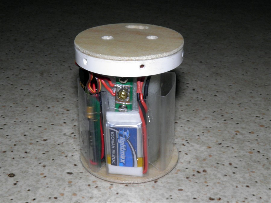
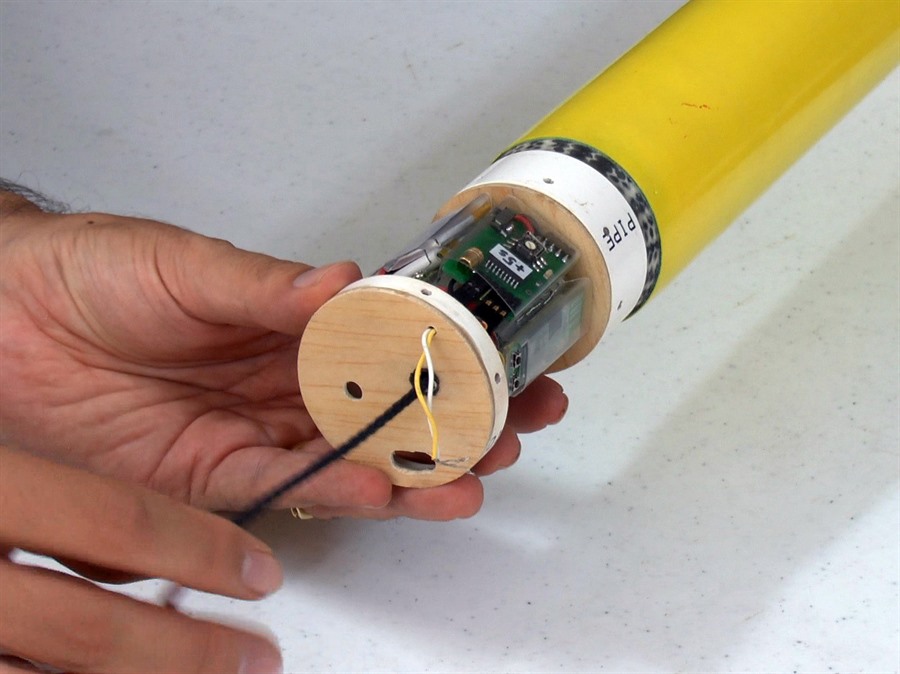
Electronics Package
The electronics package frame consists of
a central fiberglass tube with two centering
rings at either end. The centering rings are
made of a balsa-fiberglass sandwich. A PVC
ring is glued to one of the centering rings
and has 6 threaded holes to allow the
whole package to be attached to the body tube.
The 9 gram servo motor is attached to the
inside of the fiberglass tube with the servo
horn poking out to the outside.
Around the circumference of the
fiberglass tube is a set of removable
pockets made from PET plastic. Each of the
pockets contains a separate electronic
device. This allows us to remove components
easily to be reused on other rockets. The
bottom of the pockets are open so that the
electronic device can sit against the lower
centering ring. This provides support for
device against the G forces.
This circular arrangement was chosen to
allow us easy external access to the device
buttons and their displays.
The Servo Timer II, servo motor and the
zLog altimeter are all powered by the two
100mA 20C LiPos. We chose to again use a
screw switch to switch the power on to the
system as it is compact and gives a secure
connection under high G loads. The AltimeterOne used its own separate
battery for redundancy.
The Servo Timer II was re-programmed to
give a configurable time delay from 5 to 17
seconds.
PET pockets for electronics
Top view
The electronics fits snugly
inside
Battery pack
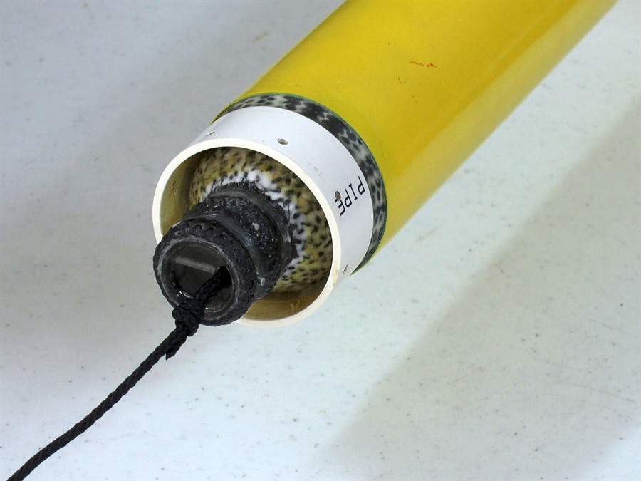
Pressure Chamber Attachment
The entire payload bay is attached to the
pressure chamber via a PVC ring that is
glued to the top of the pressure chamber.
Shadow used a similar method. The PVC ring
is the same size as used for the payload bay
body tube mandrel so it is a
nice fit. We used the PVC pipe because it is
easy to tap holes into the plastic. The
entire payload bay is attached with 8 x M3
countersunk screws.
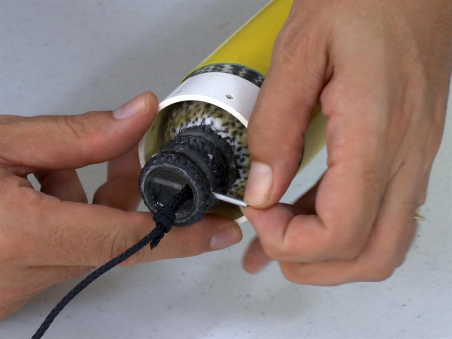
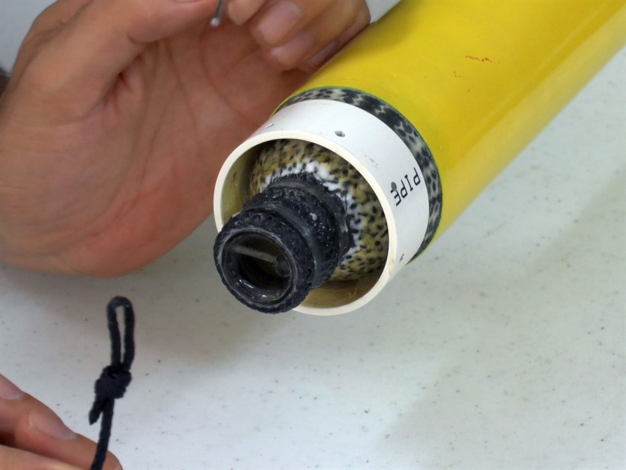
Shock cord attachment
Removing pin
Shock cord loop
Electronics package
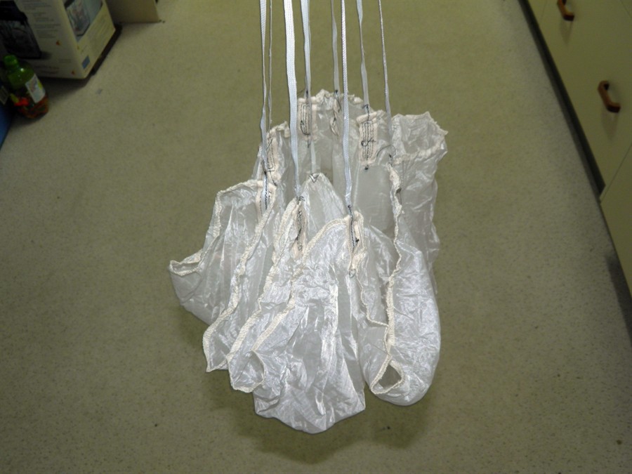
Parachute and Shock Cord
Dark Shadow uses a
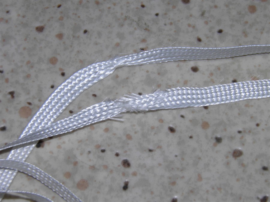
36" Aerocon parachute. The damaged nylon
shroud lines that came with the parachute were replaced with polyester
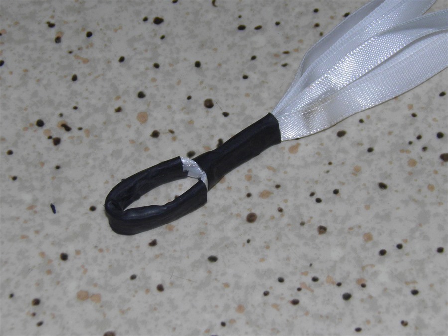
ribbons as that is all we could find. Their
size and strength are comparable to the nylon ones. We
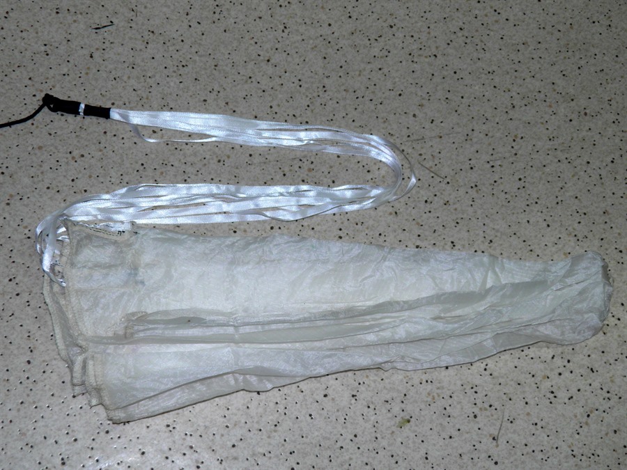
also ran the shroud lines from opposite
sides of the parachute and then created a
loop in the middle using heat shrink tubing.
The shock cord attaches to the top of the
pressure chamber so that should the payload
section break off, everything stays
connected. The shock cord is attached via a
removable pin to the top of the pressure
chamber so we can easily separate the
nosecone from the rest of the rocket. The
shock cord is made from 3mm braided nylon
cord. It has a short length of heat-shrink tubing over
a
section near the edge of the body tube to
protect it from getting cut during
deployment.
36" Aerocon Parachute
Damaged shroud lines
Shock cord loops through
nosecone
New shroud lines
Heat shrink tubing loop
Diagrams
Following are internal
detail diagrams of the deployment
mechanism.