Design
While the overall size and shape of Dark
Shadow will be similar to The Shadow, there
are a few differences for improved
performance.
- The pressure chamber will be
reinforced with carbon fiber.
- The payload section will be smaller
to reduce weight.
- The rocket will have a tail cone for
better aerodynamics.
- The fins will be thinner
- The pressure chamber bulkheads will
be integrated into the pressure chamber
design.
- The nozzle will be smaller to reduce
the overall acceleration to levels
similar to The Shadow.
- A new launcher will be built based
on the Polaron G2 electronic launcher.
- The rocket will use a tower launcher
and will not have rail buttons.
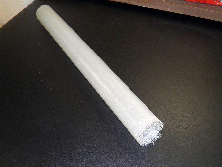
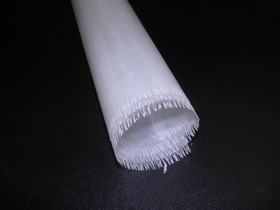
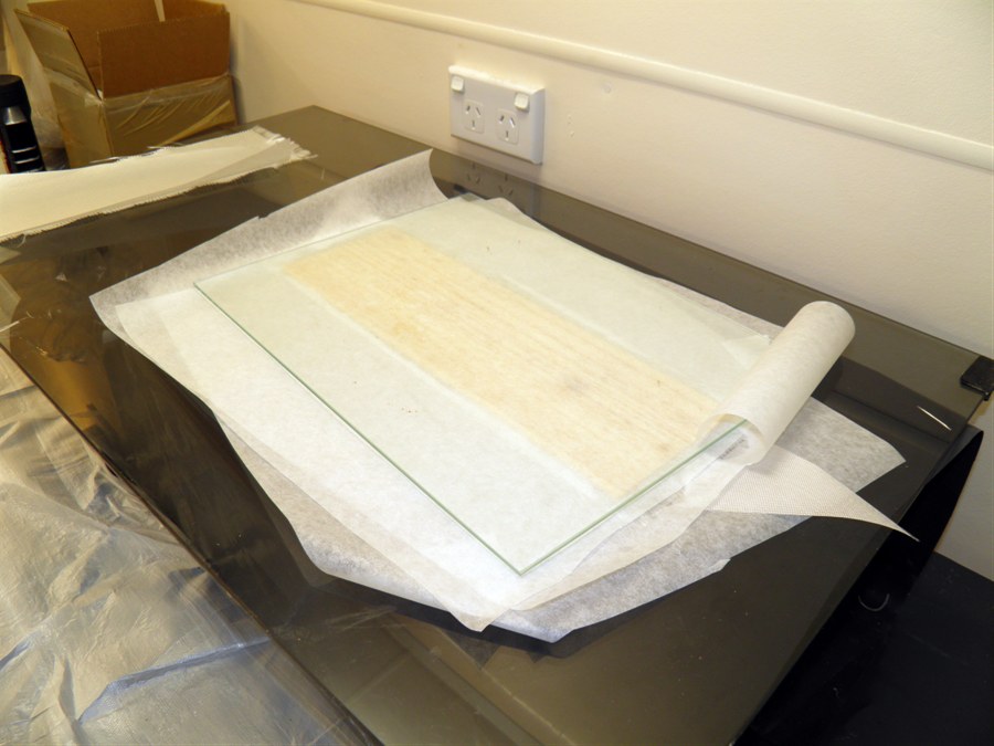
12 June 2014 - Made
a sample tube with 3 wraps of 85 gsm e-glass cloth.
This will form the inner liner for the test rocket
body.
The tube measures 525mm long
and weighs 50 grams.
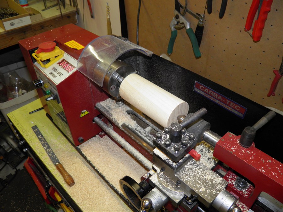
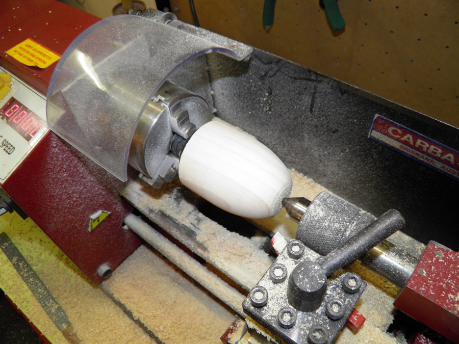
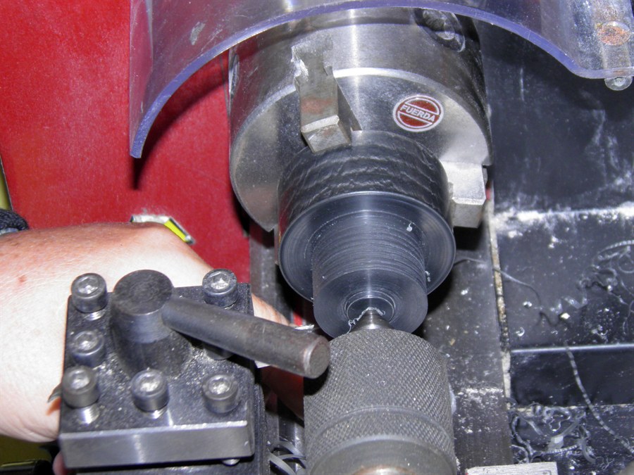
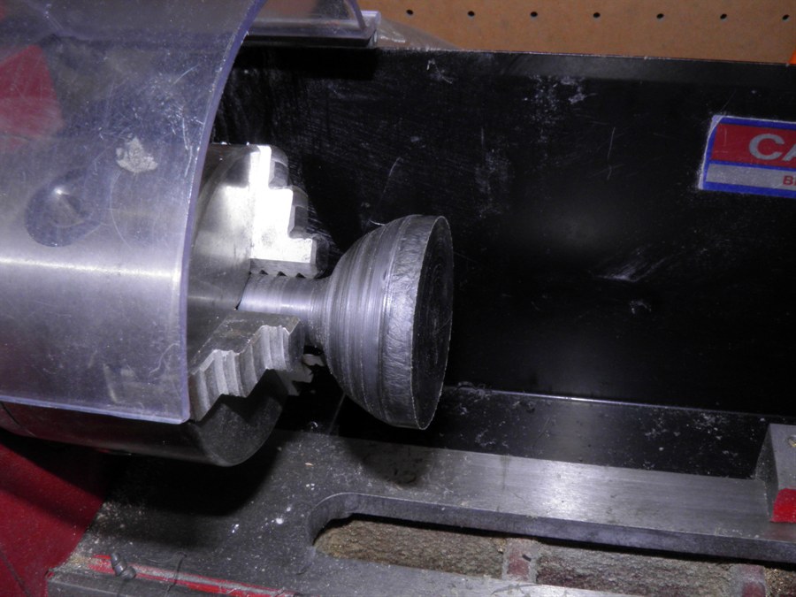
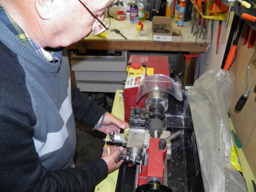
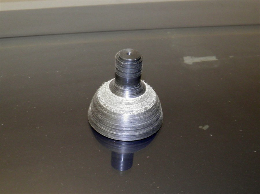
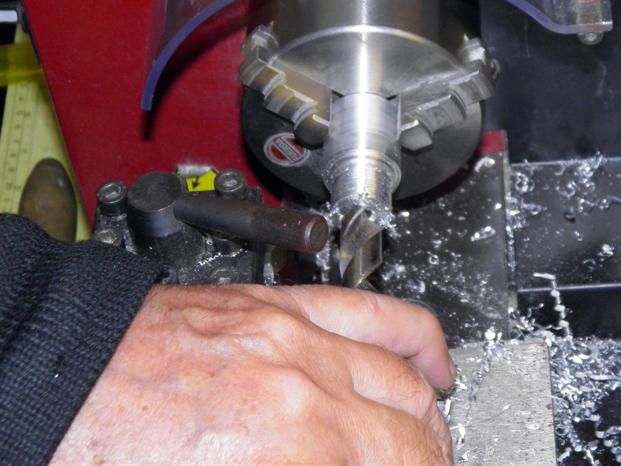
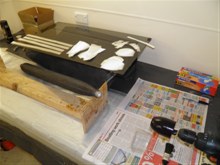
31 July 2014 -
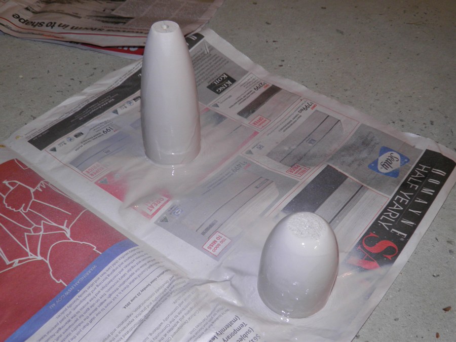
Made the tail cone plug and forward closure plugs
from wood then spray painted them with
putty, We also trimmed the ends of the tube.

Machining tailcone plug |
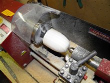
Machining forward closure plug |
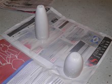
Plugs spray painted with putty. |
|

Tube as it came off the mandrel |
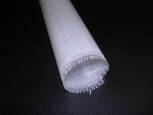
Ratty end |
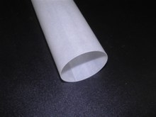
Trimmed end |
|
1 August 2014 -
We cut
threads into plug to enable it to be mounted
during fiberglassing process. we also sanded back
the
putty for a smooth finish and then applied first coat of 2-pac clear
varnish Estapol 7008.
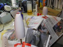
Applying 2-pac to the plugs |
|
|
|
2 August 2014 -
Sanded the first coat with 600 grit paper
and applied second coat of 2-pac to both.
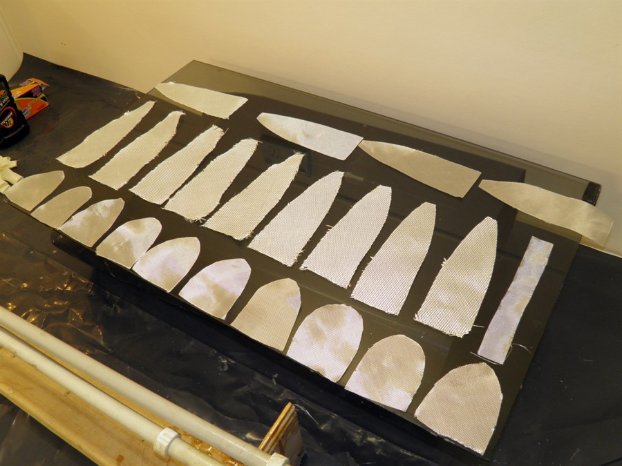
4 August 2014 -
Sanded the plug with 1000 grit paper, put on
3 balloons and using only a little bit of
talcum powder as lubricant between layers,
cut out 13 pieces of 85 gsm glass and
applied
them around the plug, this used 1 pump of epoxy.
For a smoother finish, we added a 2 cm strip
around the base of the plug that will
overlap inside the tube.

First forward closure |
|
|
|
5 August 2014 - Pulled the
forward closure off
with difficulty. The talcum powder doesn't
work very well as lubricant on the balloons.
The forward closure is just a little too big to fit
inside the tube.
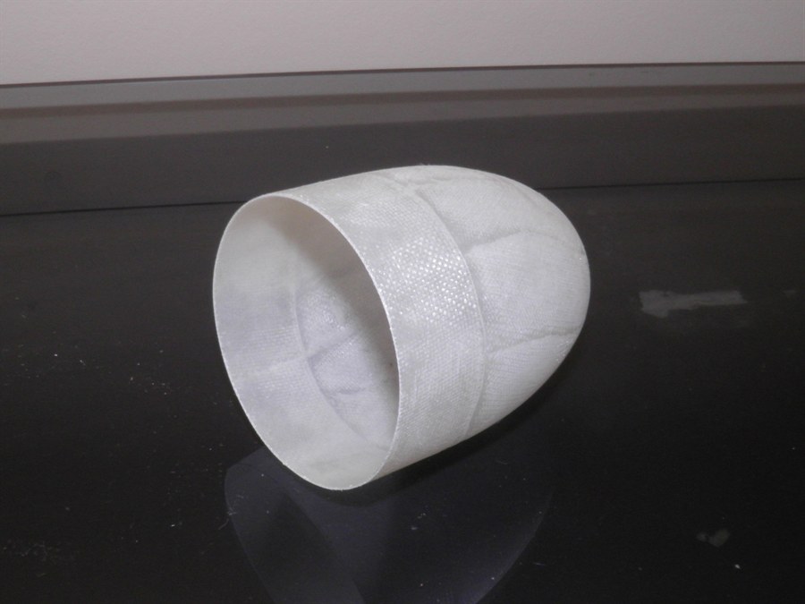
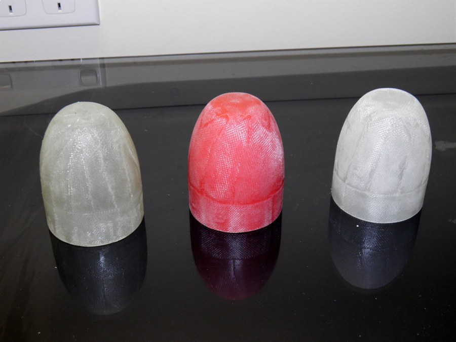
12 August 2014 - Made up
a new
forward closure with
10 gores of 85 gsm cloth and a 2cm base
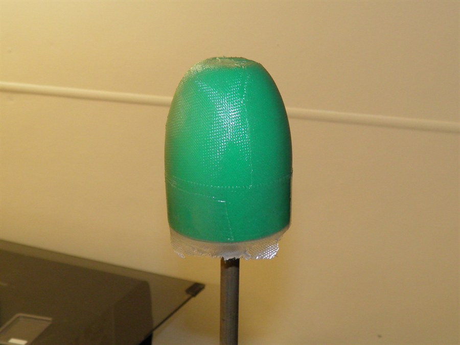
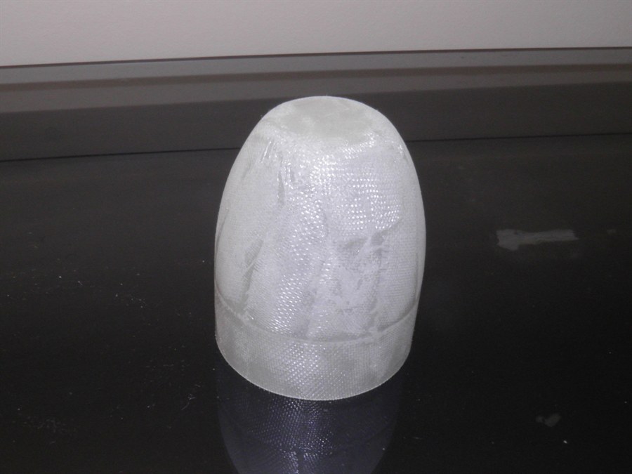
strip. We also made a new nosecone with 10 x
200gsm gores bias cut and 3 veil 85 gsm
gores for a better finish. Used 3 layers of
balloons again with silicone grease between
the balloon layers.
13 August 2014 - Took the
forward closure off the
plug. With the grease it goes off a lot
easier. The outer most balloon was not
covered in anything and as a result the
balloon had glued itself well to the inside
of the forward closure. There was no way to remove
it. Hot water, and even a steel wire brush
in the dremmel could not easily remove it.
The good news though is that the 10 gores
and one strip were the correct size to fit
snugly into the tube.
The nosecone also pulled away easily from
the plug, and this time the outer most
balloon had an very thin coat of the silicon
grease. This made it possible to remove the
balloon from inside the nosecone fairly
easily. We will try using silicone mold release on
the balloon on the next attempt.
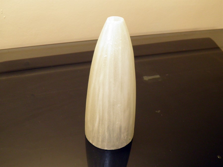
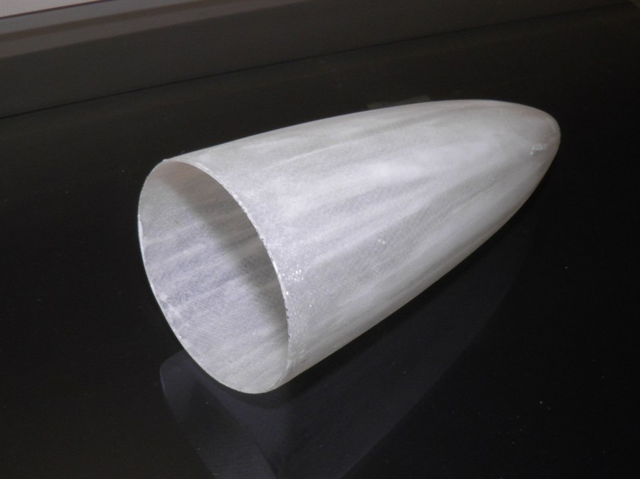
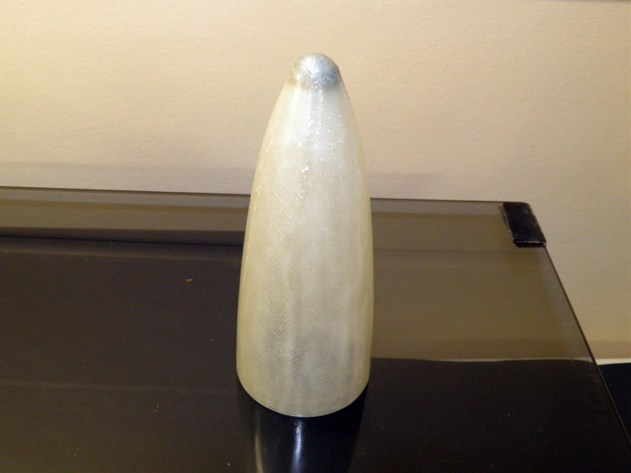
16 August 2014 - The nosecone felt a
little heavy for what it needed to be. We
can use this nosecone for other projects, So
we made up a new nosecone using only 6 x
200gsm gores + 3 x 85gsm veil gores. This
time we gave the outer most balloon a thin
coat of the silicon grease. We had also put
only two balloons on the plug.
17 August 2014 - Pulled the nosecone off
the plug very easily. So easily in fact that
the outer most balloon stayed in place. We
set up the nosecone next to a heater to get
it to fully cure
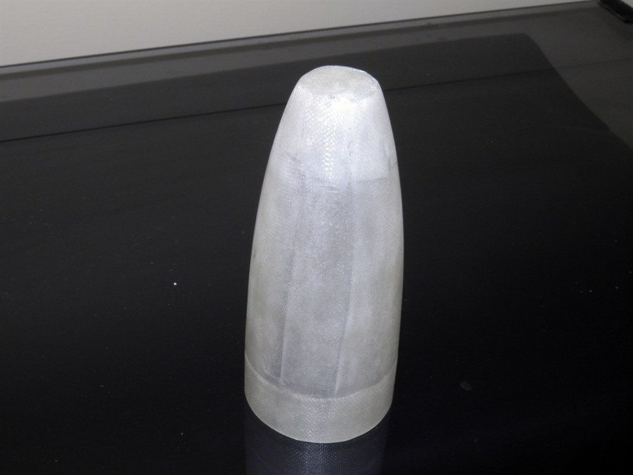
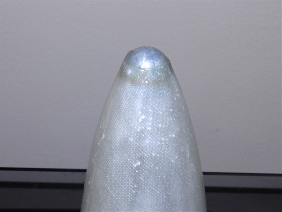
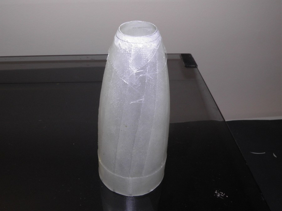
19 August 2014 - We trimmed and sanded
the nosecone down with sandpaper under a
running tap. This part of the nosecone now
weighs 19 grams. The final nosecone we are
aiming at being closer to 30 grams. The
current Shadow II nosecone weighs 67grams.
The entire Shadow II payload section
including all electronics, cameras and
parachute weighs in at 380g. We are aiming
at around half of that for Dark Shadow.
Running simulations on Shadow II, That much
weight saving would result in another 140
feet altitude.
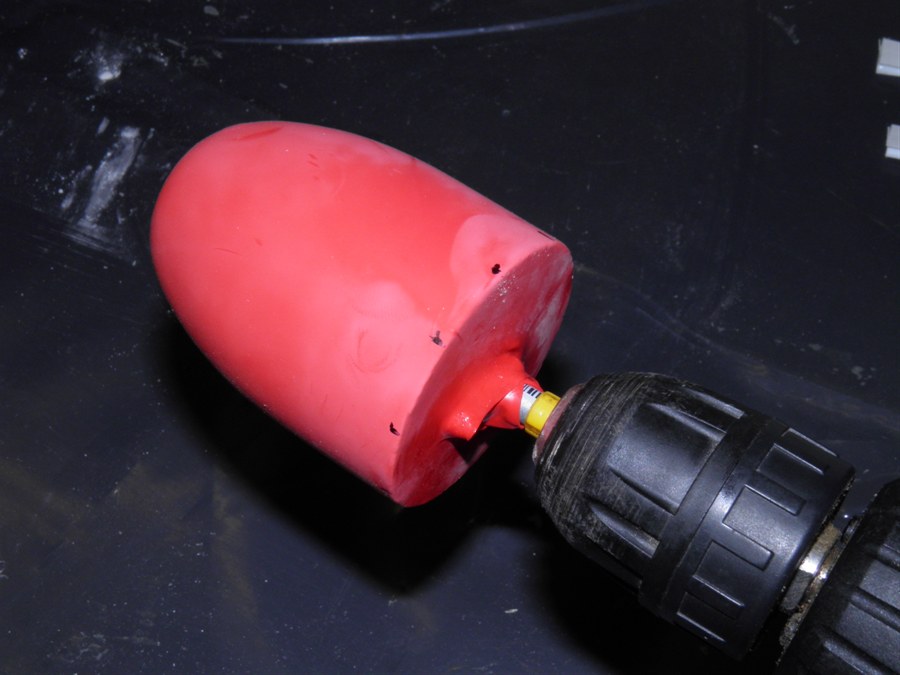
23 August 2014 - Today we machined up the
first forward closure from a chunk of PVC for the
forward closure.
We need to bring the end of the rocket to
a close and attach a mounting point for the
parachute. This part of the rocket may
experience a significant load during
parachute deploy. Probably close to an hour
later of deciding on the shape and machining
it from a lump of PVC. We ended up with a
cap that was a bit bigger than what would be
ideal. The shape is difficult to create by
hand. It also weighed in at 25g which was
pretty heavy.
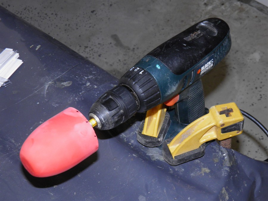
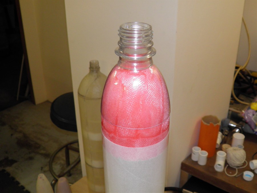
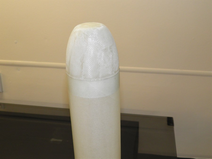
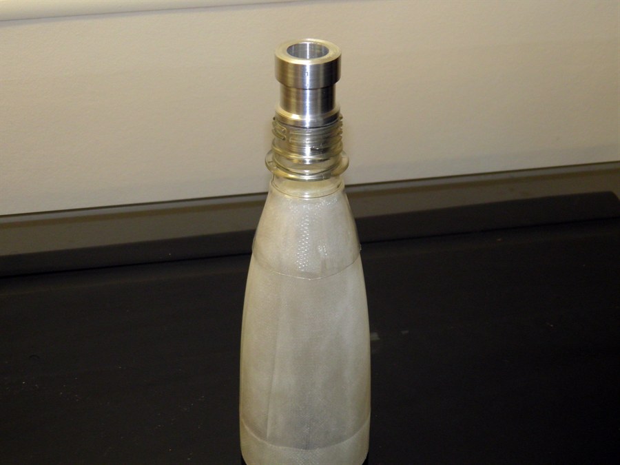
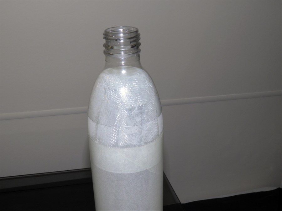
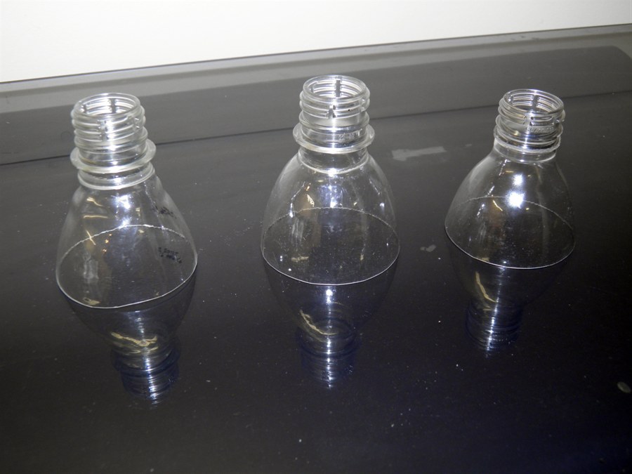
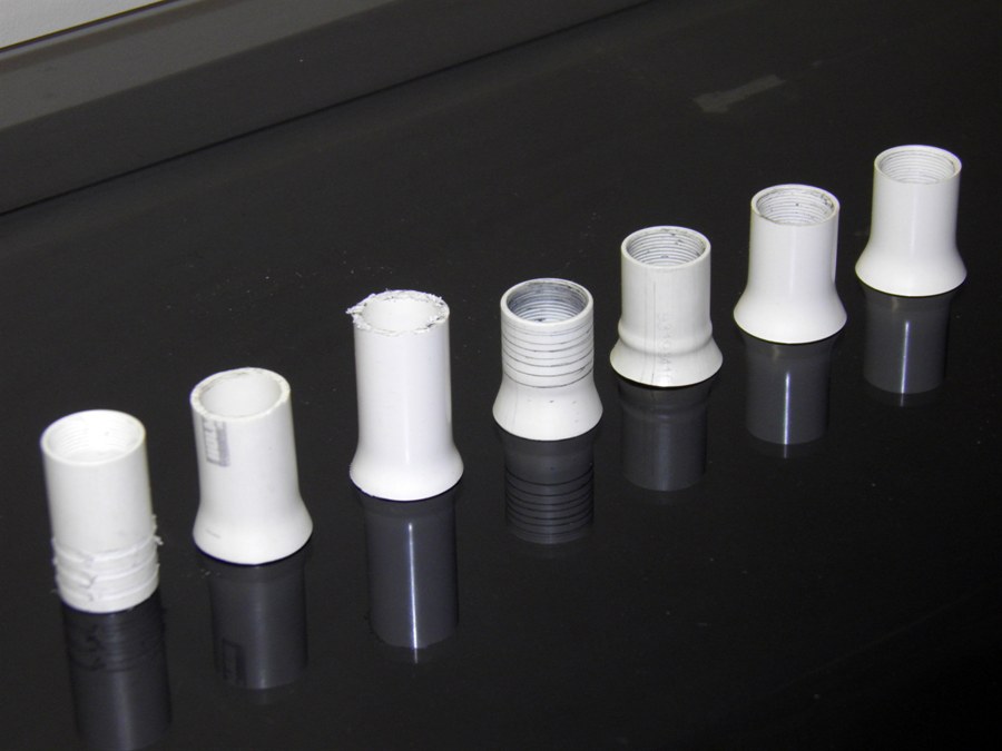
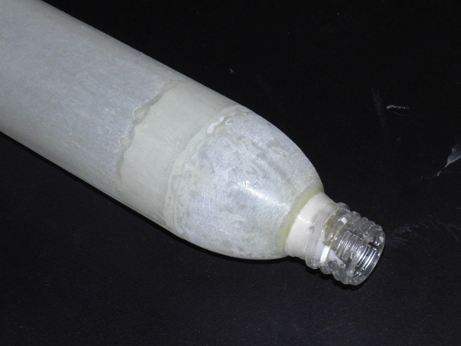
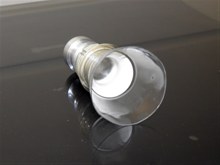
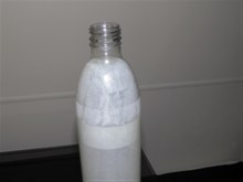
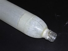
So we started talking about
alternatives, and we finally did a quick
prototype of using the top of a PET bottle
and heat shrunk over the tail cone plug. It
looked like it was going to work if some of
it was filled in with epoxy. With the carbon fiber over the top of it, it should be
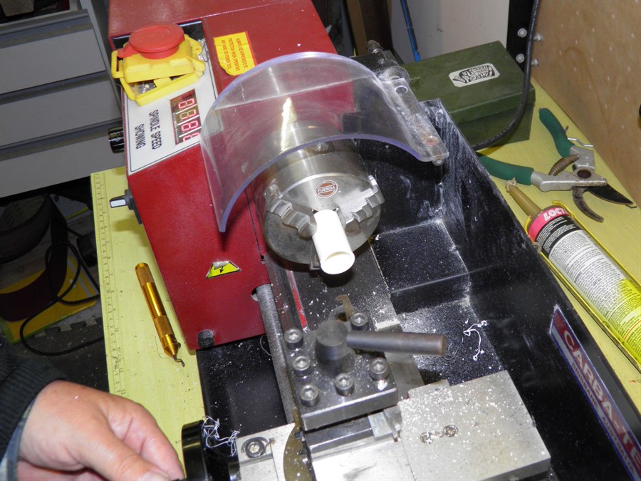
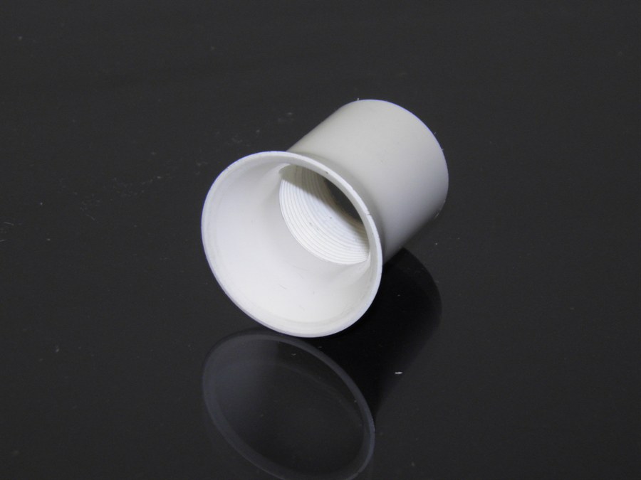
strong enough to hold in place. At this time
we turned to see if we could also use the
same concept for the nozzle end. We heated
up the top of a PVC pipe and widened it so
that it would not pass through the neck. The
idea was that we would fit the final nozzle
into that.
We are looking at using the same
technique for both the top as well as the
nozzle. The first shrinking worked fairly
well although it was a little uneven. So we
tried again with another top but this time
with a larger section of the bottle.
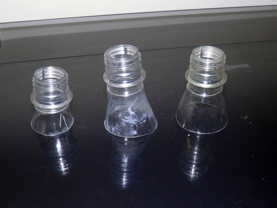
We also tried making one for forward
closure. For this we found that the bottles
with the conical top work better because
they have a wider top. We used the heat gun
to shrink it but as it was shrinking it
started moving up. So that was a fail.
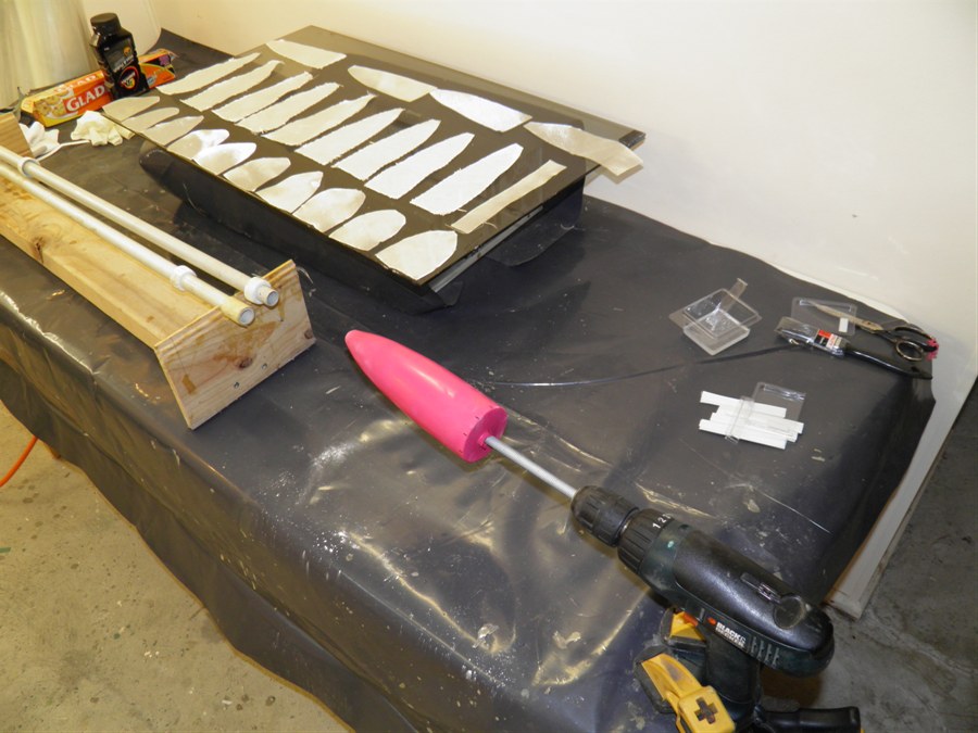
Finally we put the plug with the
fiberglass forward closure over it into the lathe,
and then using the tail stock held the top
of the bottle against the plug to prevent it
from moving up and also used the PVC pipe in
the throat to stop it from collapsing. Set
on about 200rpm, we used the heat gun to
evenly shrink the bottle over the fiberglass.
This worked really well and gave us a well
aligned bottle. The uneven bottom edge was
just trimmed off. The cap now only weighs 7
grams. We trimmed the big flange on the
bottle down with a dremmel tool too, and the
thread and other flanges on the neck will be
used to hold the carbon fiber sleeve over
the top.
24 August 2014 - We fiberglassed another
forward closure, as well as the first tail cone
today. They both used 10 gores of the 85gsm
cloth with 1 wrap of 2cm wide cloth for the
gluing edge. We again used a couple of
balloons on the plug and a thin coat of
silicone grease on top.
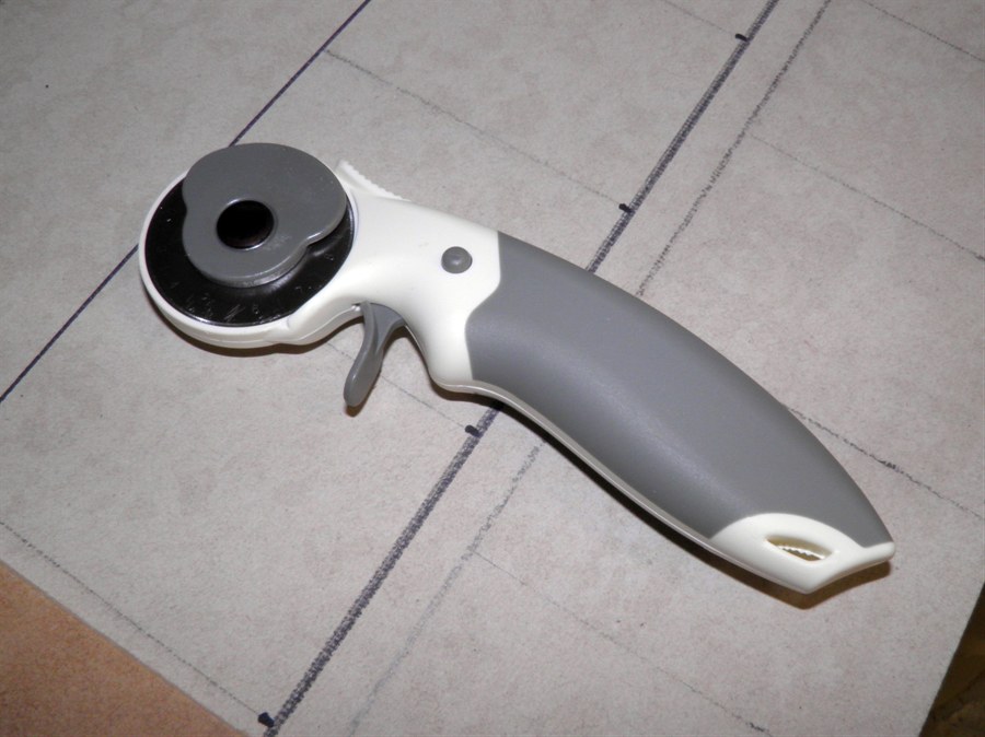
We also bought a roller cutter for
cutting the fiberglass, and it works like a
charm. I don't know how we ever managed
without it all these years.
We mixed the remainder of the epoxy with
microballoons to make it easier to sand, and
we covered the nosecone with the mixture to
fill in any holes. We then used a scraper to
remove as much of it as possible to help
reduce the sanding time.
25 August 2014 - We pulled the tail cone
and end forward closure off the molds and they again
came off easily. The forward closure was a perfect
fit into the tube, but the tail cone was a
little on the small side. We will make the
tail cone again, but this time we'll use 12
gores, 3 balloons and perhaps 1.5 wraps of
the 2cm wide strip, for a better fit.
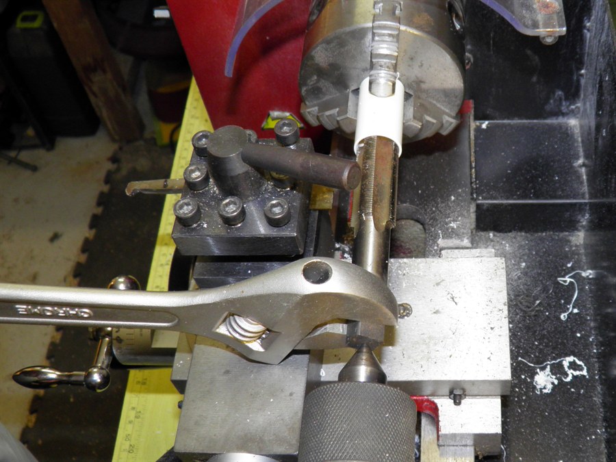
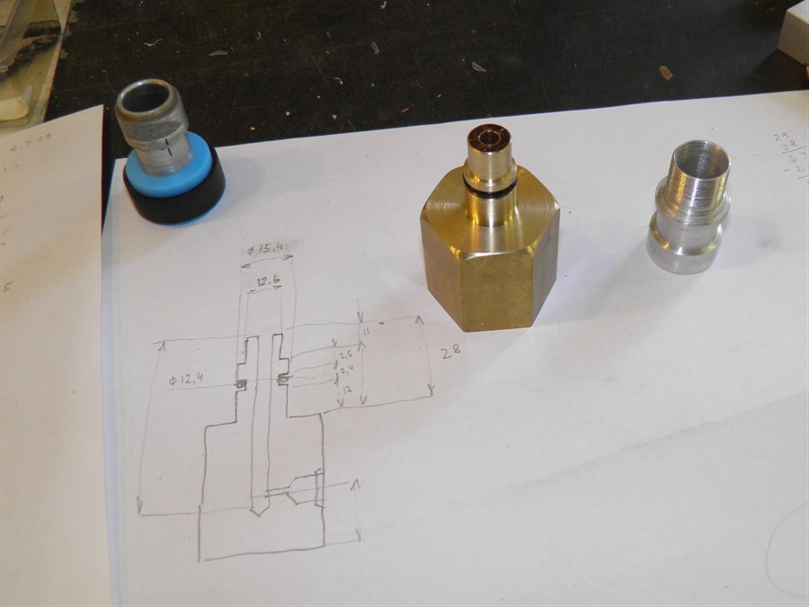
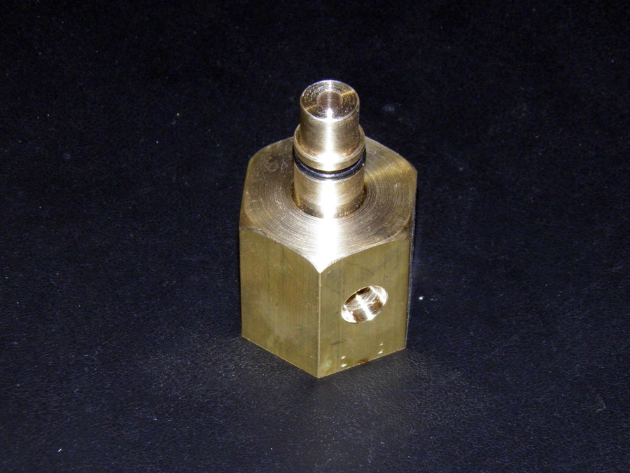
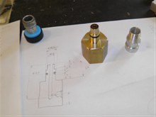
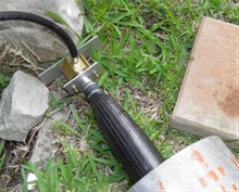
30 August 2014 - We made a nozzle insert
today from a piece of PVC pipe and enlarged
one end of it to fit inside a bottle neck.
We also cut a thread in it so that we could
screw in nozzles. Having the ability to
replace the nozzle is important in case it
gets damaged on landing. If the nozzle was
there permanently we would have to replace
the whole rocket. This time the nozzle will
not be protected like it was with the Shadow
and Shadow II, so there is higher likelihood
of damage.
We also machined up the nozzle from
alumnium. An o-ring will be sandwiched
between the insert and the nozzle. The final
nozzle diameter is 15.5mm which is about 65%
of Shadow's cross sectional area. The reason
for the reduced nozzle is that with the
expected higher pressures we want to keep
the overall acceleration down. At 600psi
with the smaller nozzle the rocket will have
acceleration similar to that of Shadow -
around 55G+. The launcher will use a
standard 15mm aluminium launch tube.
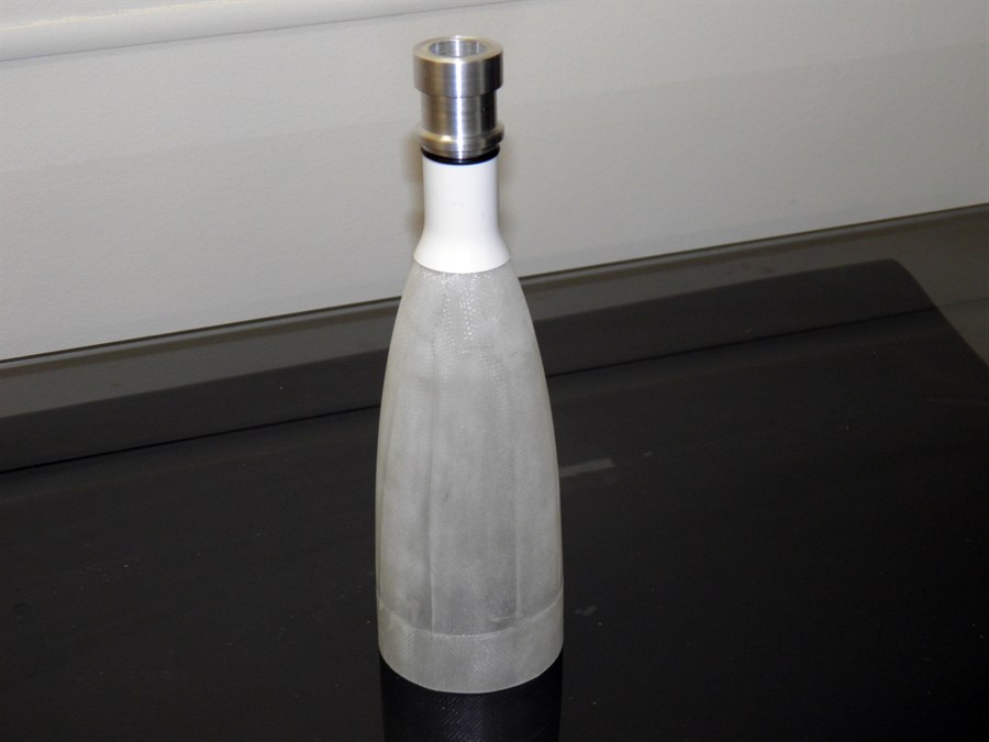
We then heat shrank a bottle neck to fit
over the tail cone. We again did this on the
lathe to get it aligned.
Next we machined up a hose adaptor so
that we could extend our hose another 5m
just to add some more distance between us
and the rocket. We now have about 17m of
hose. If the hose has a 6mm diameter
internal hole, then the total hose volume
will be in the order of 480mL. We need to
take this into account when calculating how
much air to bring to the launch site.
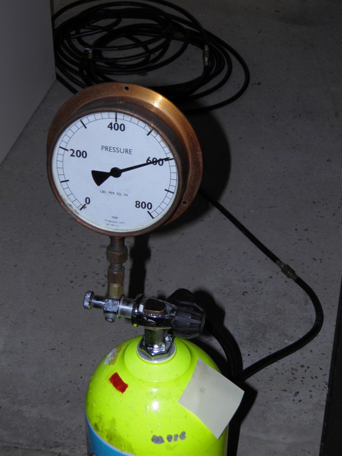
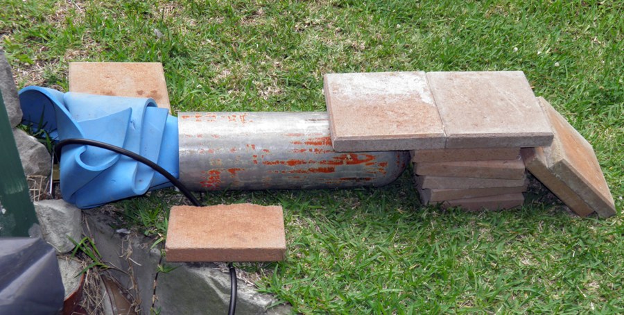
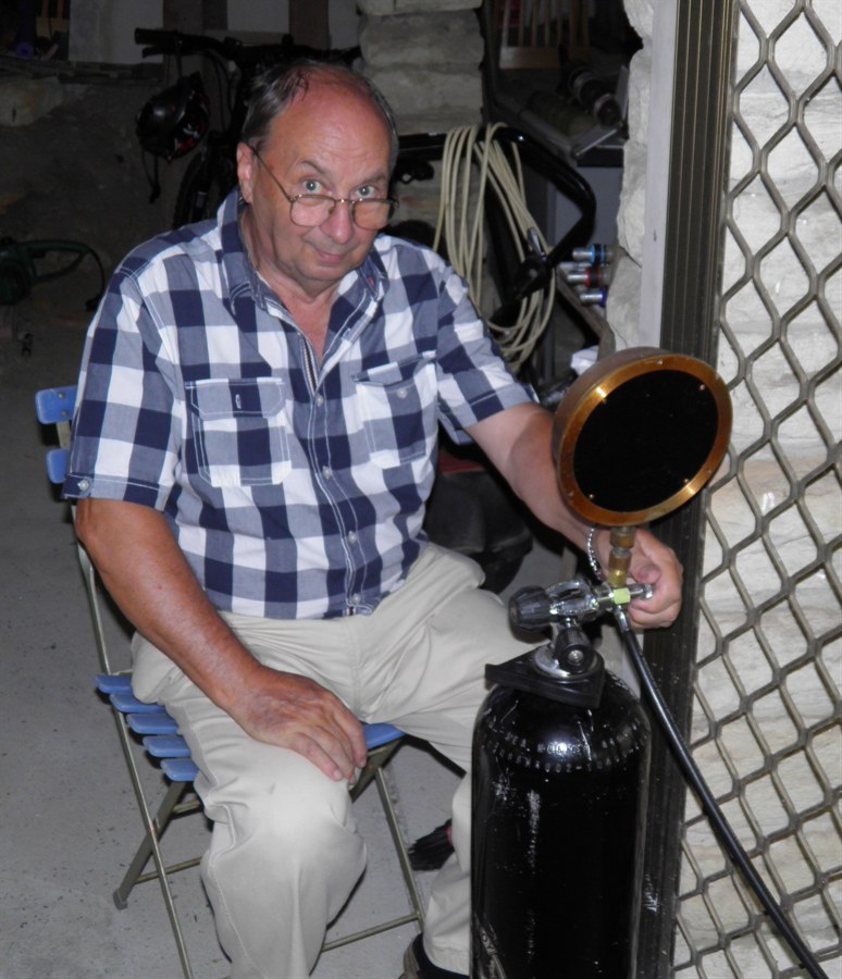
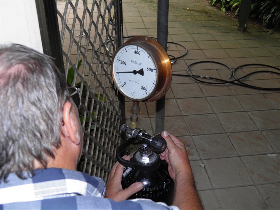
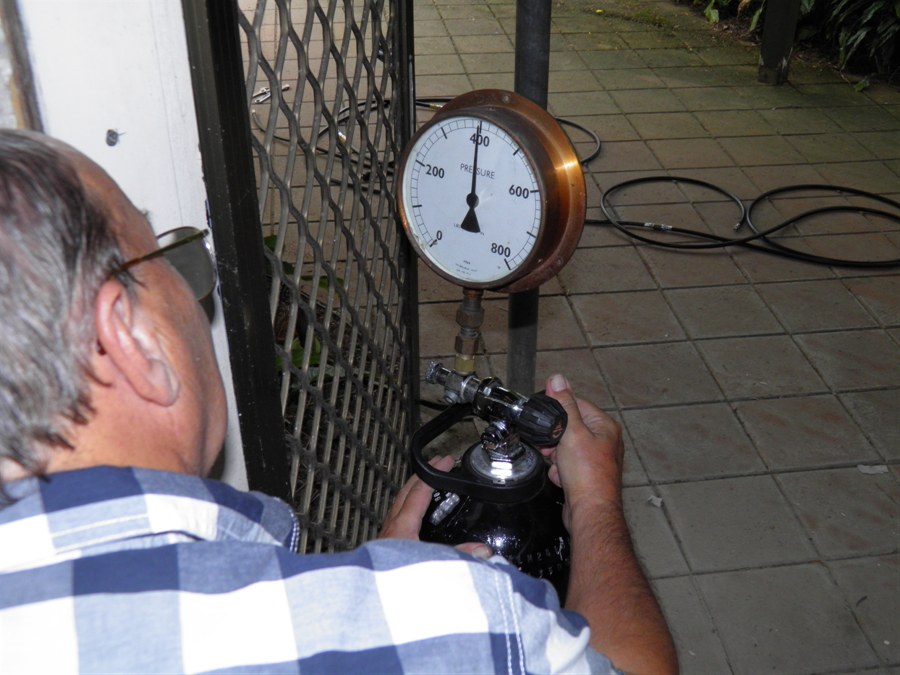
Lastly for the day we pressure tested the
hose to 600psi (~40bar). The intended
pressure for the rocket. The hose was
terminated with a quick release connector
connected to the head of regulator. We made
sure we sat behind a screen door in case the
hose intended to let go.
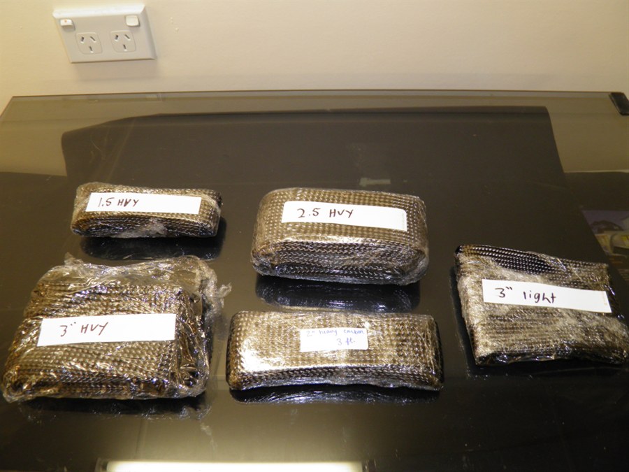
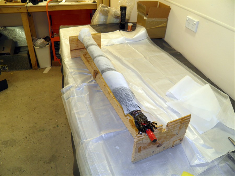
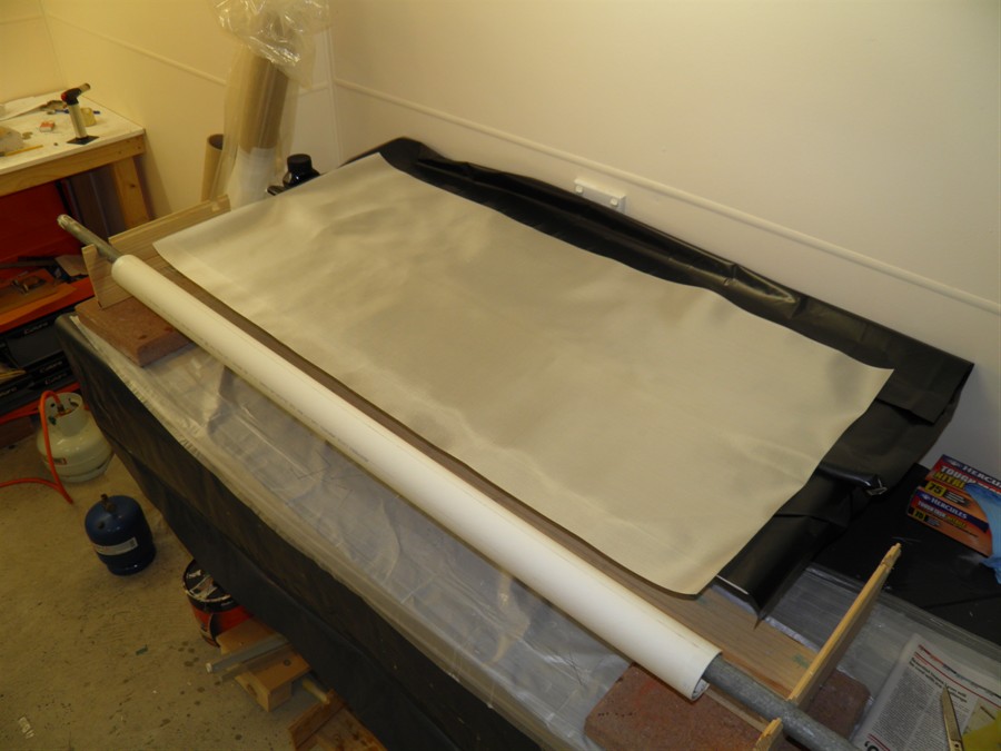
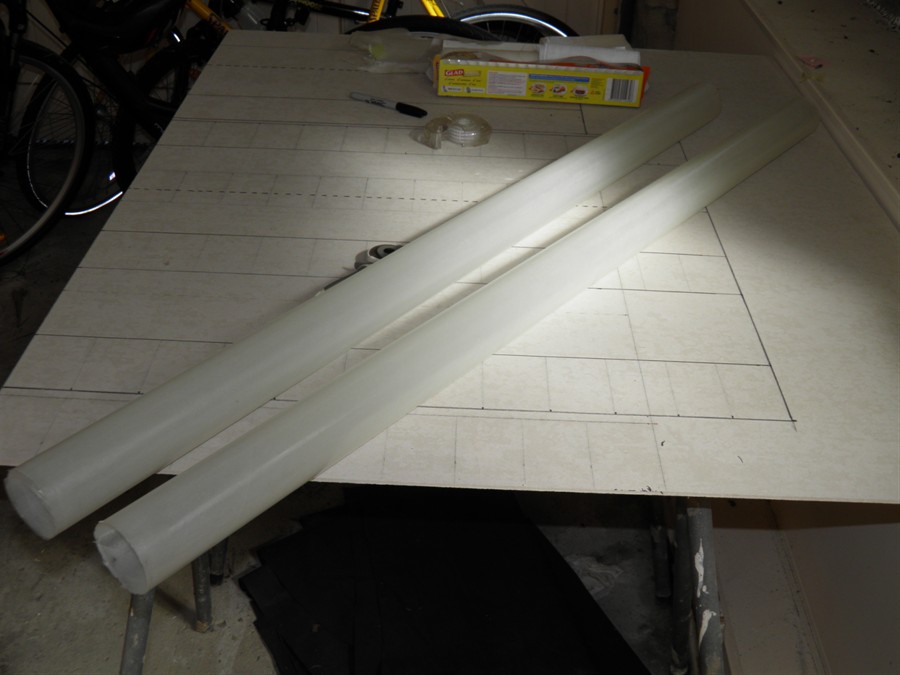
2 September 2014 - We received the carbon fiber
sleeve samples from Soller Composites. The
sleeves look very good. The heavy grade
looks like it will do the job. It will be
interesting to see how many layers are
needed to achieve the desired strength. I
would expect that even one may be enough,
but probably two. We tried threading the
tube inside the sleeves, and it looks like
the 2, 2.5 and 3 inch sleeves could be used.
We'll need to see what angle the fibers make
when the sleeve is pulled tight over the
tube. The 1.5" sleeve is too small to fit on
the tube.
3 September 2014 - Did research today on carbon
sleeves and how they are applied. It looks
like we will need to get the slow hardener
to give us enough time to work on the sleeve
for the entire rocket. This is going to be a
big job, and may need an additional person
as well. The ideal winding angle is 55
degrees from the axial axis. We will need to
put the sleeves on and measure the fiber
angles the different sized sleeves give when
pulled tight.
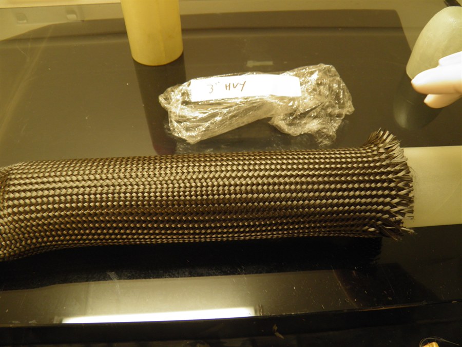
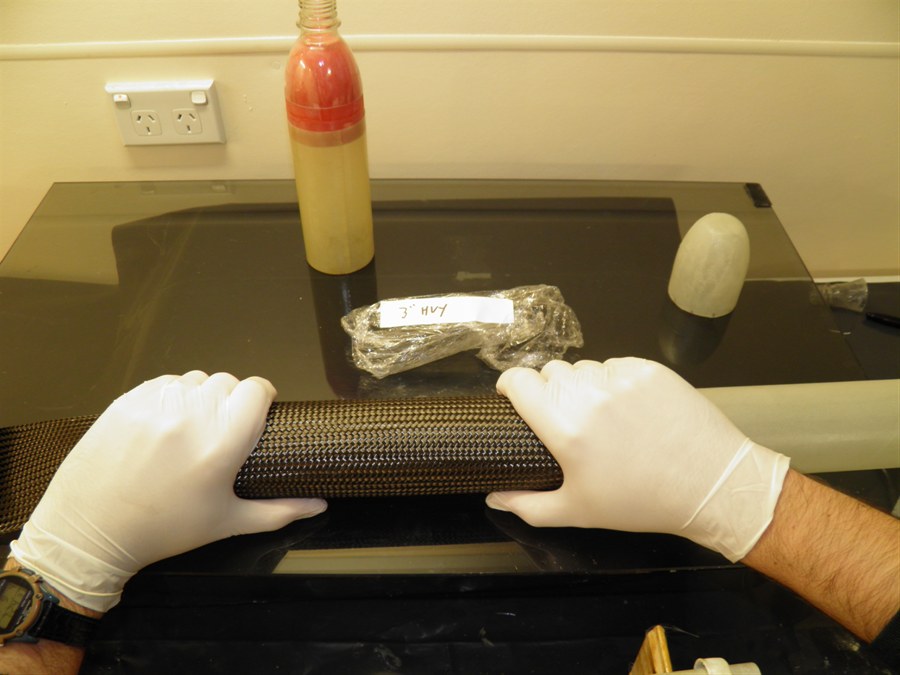
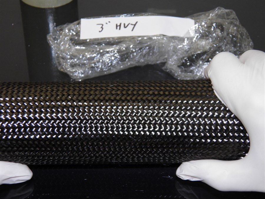
4
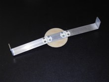
September 2014 - Stretched the
sleeves over the tube today and took
pictures of the filament orientation. We
measured the 2", 2.5" and 3" heavy sleeves
and found them to have fibers at 60, 43 and
34 degrees respectively. This means that we
will most likely go with the 2" sleeve as it
is the closest to 55 degrees. If we find
that we need a second layer, we'll then
apply the 2.5" sleeve over the top of that.
5
September 2014 -
Plugged launch tube. One of the main things that we are
concerned about is the amount of heat
generated during pressurisation of the
rocket. The glass transition temperature if
fairly low of the West systems epoxy so we
need to keep under that to reduce the
chances of failure on the pad. This means a
fairly slow fill. Unfortunately the thermal
conductivity of fiberglass is very low and
carbon fiber isn't much better, so cooling
the outside of the rocket won't help much
with reducing the temperature on the inner
wall, We need to cool it from the inside.
Simply bubbling the air through the water
won't cool it very much at all as we've seen
in our other experiments. So we are going to
try using foam to cool the air and rocket
due to the large surface area, it should
transfer the heat into the water. The other
advantage is that foam may be able to
provide additional performance boost. The
problem is how to generate the foam inside
the rocket when there is a launch tube? So we are going to plug the
launch tube just above the nozzle and below
that we will make a series of small holes
that will bubble up through the water to
make foam. When the rocket launches and gets
above the fill holes no air will come down
the launch tube. If you didn't have the
plug, the air would escape through the top
of the launch tube and out the fill holes.
The fill holes also allow you to
depressurise the rocket if needed.
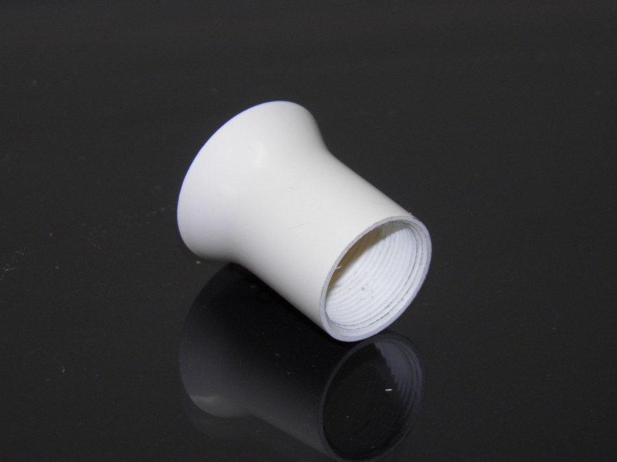
6
September 2014 - Machined up a small
aluminium cylinder that can be used inside
PVC pipe for better grip in the lathe. We
also machined up an expander for PVC pipe
out of brass bar stock. At first the
expansion angle was too great and was
causing the PVC pipe to buckle. So we
reduced the angle, We also tried preheating
the expander before putting on the PVC pipe
and also heating it up. This time the PVC
pipe expanded nicely.
Procedure for making PVC
nozzle insert:
-
Cut 60mm of PVC pipe
-
Insert support cylinder
and trim one end on lathe.
-
Counter sink the end of
the tube by hand.
-
Make a hole 17.6mm
diameter - some PVC is already this
size.
-
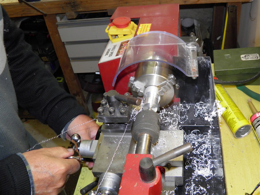
Cut thread using a tap
on the lathe. Supporting the end using
the tail stock and using an adjustable
spanner so it keeps it from turning. Go
about 15mm deep.
-
Cut off 33mm from the
threaded end with a cutting bit in the
lathe.
-
Hand counter sink other
end by hand on the lathe.
-
Insert nozzle into PVC
thread.
-
Put expander in the
lathe and preheat with a heat gun for 40
seconds (Black II, Red III) and rotate
on low RPM
-
Put PVC on expander and
continue to rotate and heat
-
When end of PVC changes
shape slightly, remove heat, stop the
lathe and push PVC onto expander up to
the stop.
-
Blow on it to cool it
down.
8
September 2014
- Made a new tail cone today using 12
gores of the 85gsm cloth and wrapped the
base 2 times. The end of the tail cone gave
me a little trouble as it wouldn't quite
adhere to the plug. So I made a small paper cone and sat it onto the tail cone to keep
all the fibers together. Although the paper
will stick to the tail cone it will be easy
to sand off.
We weighed a number of the
different components today.
9 September 2014 - We
pulled the tail cone off the plug, and the
paper cone keeping the fibers down looked
like it worked well. However, when we tried
it inside the tube, the tail cone was still
just a little too small. It maybe needed
another 1 or 2 wraps of fiberglass to make
it fit right. This is undesirable because
there would be too much of a step between
the inside and outside helping to
concentrate stress. The diameter of the
forward closure plug is 59.1mm while this one is
58.3mm. Not wanting to make up another plug,
my wife suggested, why not just wrap the
plug in a couple of layers of fiberglass to
widen it. And so we did. We added two wraps
of a wider strip of the glass, and 2 layers
of a narrower strip so 4 layers all up. This
should bring it up to about 59.2mm or so
which can then be sanded back. This will
allow us to then go back to using the 10
gores and single wrap for the tail cone.
|
|
 |
|
 |
12 September
2014 - We
epoxied a small plastic ball into the
nosecone of the rocket as this had the right
diameter. We sanded back the tail cone to
smooth out the fiberglass. This doesn't need
to be polished, as we have a balloon that
sits over it.
13 September
2014 - We
made a new tail cone using the 10 gores and
single wrap around the base. Only two
balloons were used for this plug. This time
we again used the paper cone on top to keep
the fibers together.
14 September
2014 - We
removed the tail cone from the plug and it
separated fairly easily. Test fitting it
inside the tube gave very good results and
should be good to use for the test chamber.
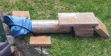
Day 150 Plugged launch tube
experiment. See Day 150
update. We wanted to see if we could get foam generated inside a
rocket during filling while using a full bore nozzle and full
length launch tube. So we adapted a normal Clark Cable-tie
launcher and drilled 6 holes near the nozzle inside the rocket.
This would allow air to bubble up through the water and form
foam. Even back in 2007 Damo was using holes in the bottom of
his launch tube, but the launch tube was not plugged. There are two problems with this approach. The air wants
to flow up the launch tube instead of through the holes, and
once launched the air can escape out of the holes through the
launch tube. So we simply plugged the launch tube above the
little holes. This way as the rocket moves up the launch tube,
the air can't escape from the rocket.
One disadvantage is that you can't use ARB boosters with the
plugged tube.
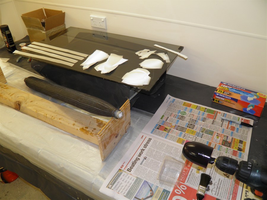
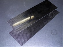
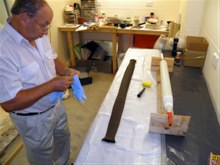
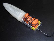
3 December 2014 - We
received 2 carbon fiber plates today from
hobby king. These are 1.5x300x100mm and
should be sufficient to make up to four
fins. (3 fins + 1 spare)
 |
|
|
|
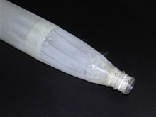
10 December 2014 -
We prepared the shrunken plastic bottle for
gluing by cutting little notches around the
edge. The idea here is to help spread the
forces along the interface between the
plastic bottle and the fiberglass shell. We
also drilled a number of small 1.5mm holes
into the plastic bottle to help get it to
"key" with the epoxy. We removed most of the
bottle flange with a sander in the dremmel
which will allow the carbon fiber to conform
better to the shape. We left a little bit as
it will help grip the CF sleeve better. We
also sanded the entire inside and outside of
the bottle with 120grit sandpaper for better
adhesion. We then glued the bottle top to
the fiberglass shell with 24hr Araldite. We
filled the top of the bottle with more epoxy
this time mixed with microballoons to help
provide support for the top of the pressure
chamber. We then added a weight to the top
to help compress the join.
We also glued the PVC nozzle insert into
the tail shrunken bottle neck. Again we
mostly removed the bottle flange for better
sleeve conformity, and cut a series of notches
along the edge. We also used the 24Hr
araldite for this.
11 December 2014 -
We glued the bottle neck with PVC insert to
the fiberglass tailcone and again added
weight on top to help seat it
properly.
17 December 2014 - Glued tail cone to body.
18 December 2014 -
We sanded the joins, and filled the gaps
with epoxy and microballoons. We are trying
to reduce the chance of little air pockets
developing after we put the carbon fiber
sleeve on.
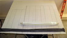
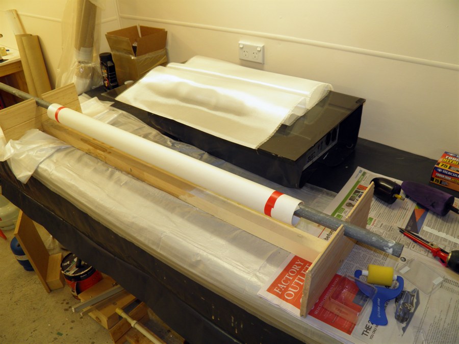
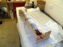
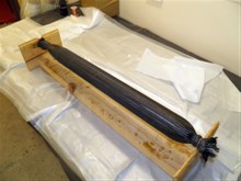
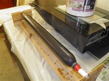
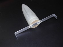
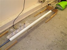
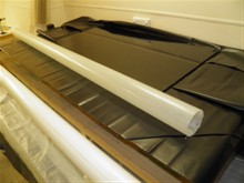
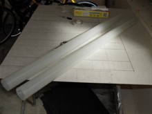
Length of sleeve compared to
pressure chamber |
 |
 |
 |
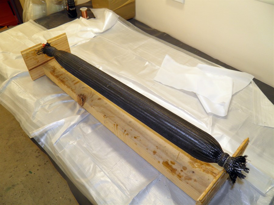
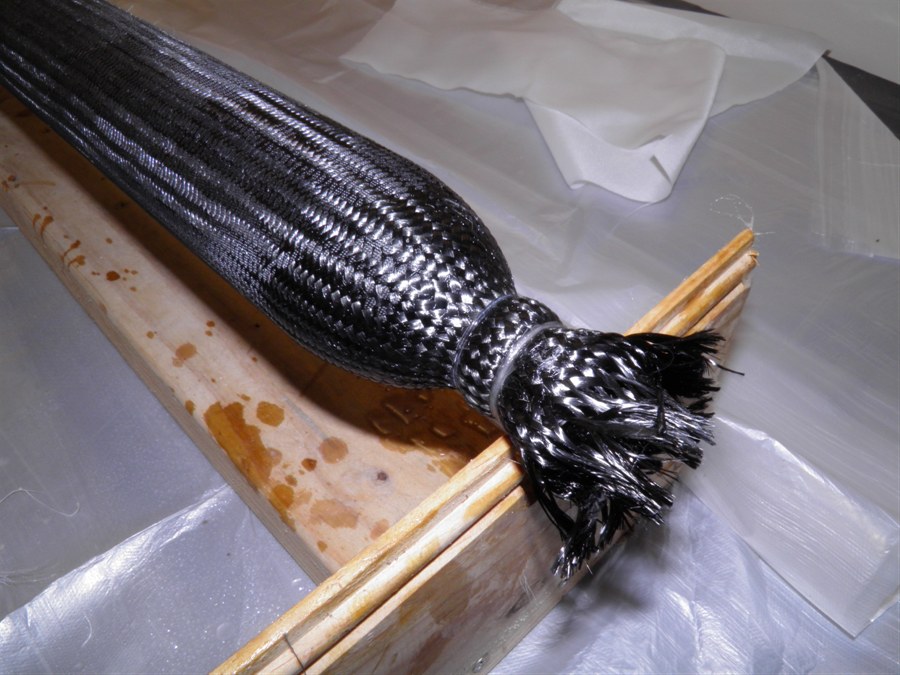
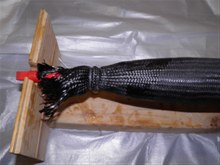
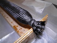
19 December 2014
- We wrapped the fiberglass pressure
chamber with
2" heavy CF sleeve and, used 3 pumps of
the epoxy which was not enough. We used
peel ply in a spiral fashion around the CF
to give it a better finish. We held the
sleeve down
with wire while pulling it tight and used fiberglass strands to help
hold CF sleeve in place. Next time we will use
wire on everything, and then apply the fiberglass after the CF has hardened.
We used the tap to hold the nozzle
end of rocket and a piece of PVC pipe to
hold the other end while laying it up. We also made the nozzle
seat for the launcher.
Preparing to pull the sleeve on |
Sleeve in place with peel ply
applied |
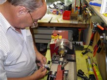
Machining nozzle seat |
Nozzle seat completed. |
20 December 2014
- We trimmed the excess CF from test
pressure chamber. This was just done with a
hacksaw. We also
cut out the forward closure gores x 20. But
when we tried making up another forward
closure with them, we failed miserably. This
fiberglass is just too stiff to
conform nicely to the shape like the
previous glass. We'll have to get more of
the original 85gsm glass. We also filled the top of neck with extra
epoxy. We wrapped extra fiberglass threads
around end of the sleeve to replace wire that
was there holding things in place
temporarily.
Test pressure chamber with
peel ply removed. |
Excess CF at one end
|
And at the other.
|
Getting ready to fiberglass
forward closure. |
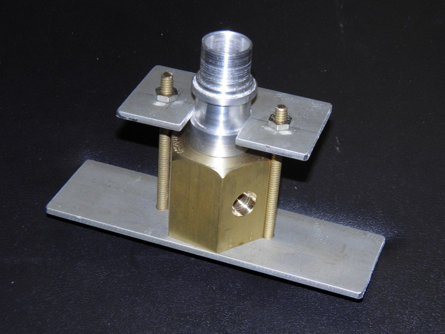
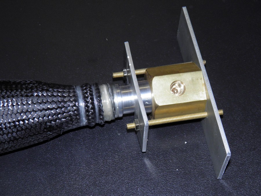
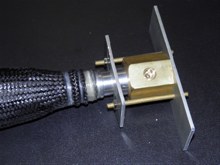
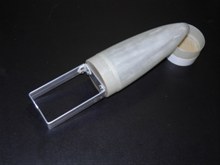
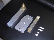
23 December 2014 -
We made a temporary nozzle
retainer for doing pressure tests. This
basically consists of two plates with a pair
of bolts holding the nozzle down against the
nozzle seat. We also tapped 2
mounting holes in the bottom of the nozzle
seat for later mounting on the launcher.
24 December 2014 -
Made up more laminated
balsa sandwiches These have a 200gsm cloth
overlayed with bias cut 84gsm cloth over the
outside. We use any left over epoxy for
these sandwiches. We also made the payload bay body tube
with 6 wraps
84 gsm e-glass. Length of glass 1150mm.
Finally we added
glass filament reinforcement to test
chamber ends to strengthen them.
25 December 2014 - We worked on the deployment
mechanism prototype today. We wanted to make
some improvements over Shadow's deployment
mechanism. The one biggest drawback with the
previous design was that it was friction
dependant. The nosecone had to be tight
enough to not separate on burn out, but not
too tight so the piston could push it out.
The friction properties varied based on
temperature and humidity. The other problem
was the shock cord got in the way of the
piston and so had to be attached to the
payload bay wall. There was always a danger that
the payload bay could be ripped off the
pressure chamber. The piston mechanism was
also quite long and heavy. The new system
gets rid of the piston, allows the shock
cord to be attached to the main pressure
chamber, is positively retained (not
friction dependant) and is shorter and
lighter. We'll do a detailed writeup of the
entire mechanism once the final design is
complete.
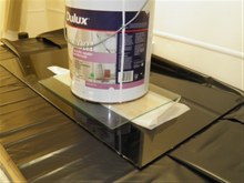
We also pressure tested the test
chamber to 100psi but 2 leaks in the body
were found. These must have come from tiny
holes in the rocket body. So in an attempt
to fix this we applied another coat of
epoxy to the outside.
We made a nosecone bulkhead and glued it into
a coupler we had made previously for the
Shadow project. We also added the swinging
grapple arms to the deployment mechanism
prototype.
|
|
|
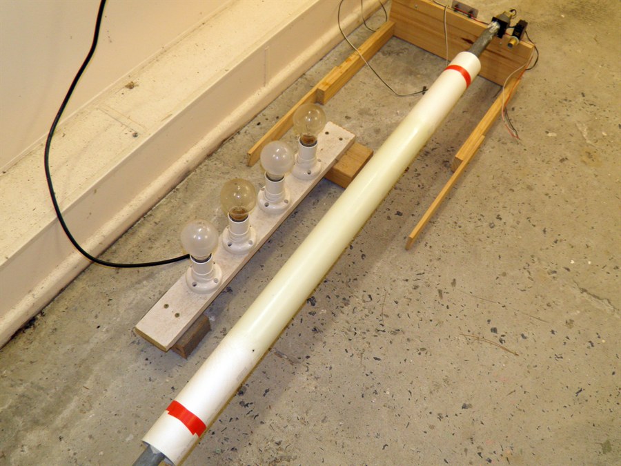
Getting ready for low pressure
leak test
|
Pressurising to 100psi - couple
of small leaks
in the body itself |
Painting the surface with more
epoxy
to stop the leaks. |
Parachute grapple arms |
Grapple arms open |
Grapple arms closed |
26
December 2014
- After the epoxy had cured we pressure tested the
test chamber to 100psi and to great relief
it was without leaks. We also tested
prototype deployment mechanism to see if the
arms would let go of the parachute.
Originally we were going to use a spring
mechanism to swing the arms open, but in
testing it was found that this is
unnecessary and the arms let go of the
parachute freely.
27 December 2014 -
We bought aluminium 30x50x2mm box section
today along with another PVC pipe.
The box section will become the basis of the
launcher and the PVC pipe will be machined
down to form the long tube coupler mandrel.
28 December 2014 -
Today we tested the test pressure chamber to
650psi (45 bar) and it still held. :) We
couldn't go higher because we only tested
the hoses to 600psi previously. There were
no visible stress markings on the pressure
chamber. So we are not sure how close to the
limit that is. We also rolled the first of
the long tubes that will make up the basis
of the rocket. The tube is made of almost 3
wraps of the 84gsm glass cloth The cloth is
1150mm long. We used 3 pumps of epoxy. We
also used a cheap roller that ended up
losing bits of it. We also started gathering
up all the components for the launcher.
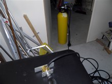
|
|
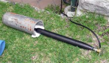
Putting the test chamber in a
scuba tank. |
We put the connection against
the house
in case things went flying |
Ready for the test |
Rolling new full length tube |
Making up fiberglass-balsa
sandwich
for bulk heads |
|
|
29 December 2014
- We ordered a pair of
Aerocon 36" parachutes today. With the
higher performance of this rocket we wanted
to have a more sturdy parachute for
potentially higher speed deploys. We also
ordered 30 feet of the 2" heavy carbon
sleeve from
Soller Composites.
We also tested a prototype of the release
mechanism. After spending several days of
trying to figure out a latch, lever and
servo mechanism to release the grapple arms,
we decided to just use a loop of wire hooked
over the servo motor horn. By hooking the
wire over the axel of the horn it can hold
quite a bit of force. When the servo motor
turns, it just slips the wire off releasing
the grapple arms. We can also easily adjust
the length of this loop.
We made some more progress on the
launcher making a few of the smaller
components and the lever arm.
We pulled the long tube off the
mandrel ,but are less than happy with the
result. Because of the size of cloth we
weren't able to quite get 3 complete
wraps (about 1 cm short) and the frilly
edges left a few bubble pockets along the
length.. While this would have been fine for
a shorter tube, we need a bit more rigidity
when we pull the sleeve over it. The cheap
roller also left quite a few little bumps on
the tube, presumably bits of the foam. So we
will make up another tube with the frills
cut off, and then add another single wrap as
a second piece. This should also help reduce
the chance of porosity in the tube.
Parachute inside grapple arms |

Hold down wire |

Components for launcher |
Less than satisfactory first
tube |
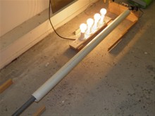
30 December 2014
- We rolled a second full length tube
today with 4 wraps of the 85gsm cloth. This
time we used the better quality foam roller
and the results were much better. We also
continued to work on the launcher. The main
base components are now mostly complete. We
are using a brass insert in the lever arm to
add extra strength to the nozzle contacting
surface.

Rolling full length tube |
Starting launcher construction |
|
|
31 December 2014
- Rolled second full length tube the
same way as the first. Made up the base of
launcher and attached it to the bottom of
the box section.
Second full length tube |
Old and new tubes |
|
|
Continue to Part 2...
Dark Shadow Parachute Deployment Mechansim |