For illustrative purposes the diagrams below have been simplified. Click on the
diagrams for a larger version.
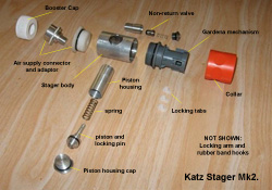 |
A photograph showing the actual components. |
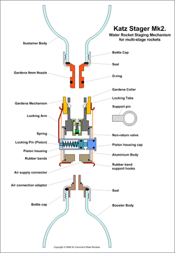 |
This diagram shows the main components of the stager. It is based on an off-the-shelf
Gardena hose attachment with the hose fitting and spring removed.
Primary construction materials are plastic and aluminium. The majority of threads
are not shown in order to simplify the diagrams.
The stager simply screws to the top of a booster.
|
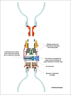 |
In the unpressurised state the piston spring keeps the piston and locking pin retracted
inside the piston housing. The piston housing cap prevents the piston from moving
too far back and allows access to the piston should the spring or o-ring need to
be replaced.
The piston housing has a small hole in the side that allows pressurised air to enter
above the piston head. The piston head is designed so that it creates a small space
near the hole.
With the locking pin retracted the locking arm and collar are free to move downward.
Tension provided by the rubber bands ensures positive pressure on the collar and
hence locking arm to keep it open.
The air supply connector and adaptor at the bottom of the stager allow a strong
sealed mechanical connection to the top of the booster.
|
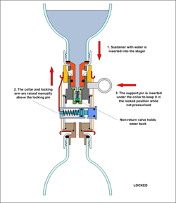 |
Next, the sustainer with water is placed into the stager.
The collar is raised into the locked position manually, and the locking tabs in
the Gardena mechanism engage into the sustainer nozzle groove.
Because the locking pin is still retracted, a temporary support pin is placed under
the collar to keep it locked.
The non-return valve just under the nozzle prevents any water from leaking into
the booster. |
 |
When pressurisation starts, the air from the booster enters the stager body. Most
of the air flows around the piston housing, through the non-return valve and into
the sustainer. The positive pressure difference in the stager body keeps the water
from flowing out through the non-return valve. When pressure equalizes the spring
in the non-return valve keeps it shut.
Some of the air from the booster also enters the air inlet hole in the piston housing.
As this pressure grows, the piston spring is compressed as the other side of the
piston only has atmospheric pressure acting on it. As a result of this the locking
pin extends out of the piston housing. For our prototype this happened between 20
and 30psi.
When the locking pin is extended sufficiently pressurisation is stopped at that
point and the support ring can be removed. The locking arm is now resting on top
of the locking pin keeping the Gardena mechanism in the locked position.
When everyone is clear of the rocket, the pressurisation can then continue to the
full launch pressure. The pressure in the booster continues to hold the locking
pin extended. |
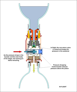 |
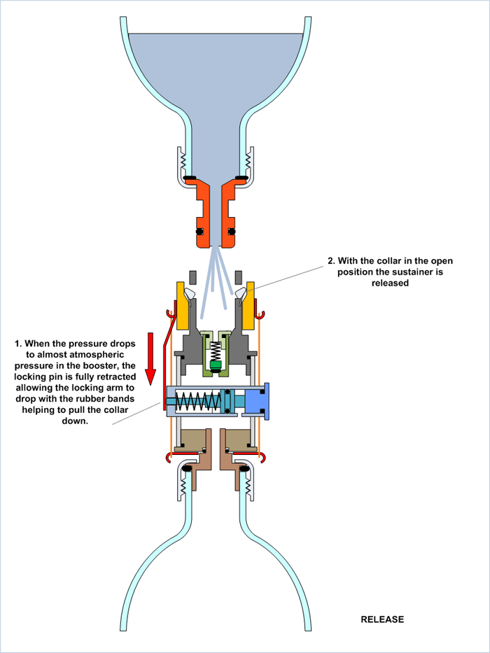
After launch the booster pressure starts to drop. As the booster pressure drops
to around the 10-20psi mark the locking pin starts to retract because of the spring.
(The retraction pressure is lower than the extension pressure on the piston due
to frictional effects between the locking pin and the locking arm.
The non-return valve remains closed due to the increasing pressure difference between
the sustainer and stager body. |
 |
When the locking pin has retracted far enough, the locking arm is free to move downwards
under the tension of the rubber bands and pulling the collar with it.
This releases the sustainer.
|
Ground Tests:
Early Flight Tests:
The design of this stager was inspired from Trevor's original piston based TDD.
There are many examples of various staging mechanisms developed by water rocketeers
over the years. Here are just a few examples of the variety developed: