V1.6 Overview
This flight computer (FC) was designed
primarily to provide timing for parachute deployment and
staging of multistage water rockets. The FC can drive one or
two standard RC servomotors that are used to release latches
on
recovery systems. The timing can be initiated
in a variety of ways such as
an acceleration switches,
pressure switches or deceleration detection. The FC
can be used on
both simple or more advanced
rockets.
Water Rocket Flight Computer V1.6
Features
The FC has the following main
features:
- Dual RC servo
motor control.
- 7segment LED
display indicating status information.
- Built in launch
detect G-switch (optional).
- External launch
detect / burnout / negative-G trigger input
- Buzzer for
indicating status and helping to locate lost rockets
- EEPROM used to
store settings while power is turned off
- 15 configurable
control parameters
These
instructions give an example of how to use the flight
computer in a parachute deployment mechanism.
Changes from V1.5
- The altimeter power connector has been removed. The
altimeter can still be powered via the second servo
connector. If both servos and altimeter are used then
the second servo can be connected to the altimeter's pass through
connector to connect the second servo motor.
- The PCB is now double sided resulting in less
weight and 25% smaller area. The PCB is also only 27mm
wide allowing it to be used inside T-8 and T-12 FTC
tubing.
- The timing parameters have been changed to represent
seconds directly rather than the more confusing
offset/multiplier technique used in V1.5. Although the
direct setting reduces the range of values possible,
they should cover the vast majority of situations as
used in the real world. The timing for both D1 and D2
phases can now be set between 0.1 and 99.9 seconds in
0.1 second increments.
- The setting of the two delay parameters in the
Normal mode have been removed and the FC now simply
requires one press of the ARM button to ARM it. This was
done to make it simpler for the rocketeer to use
in the field, and prevent accidental timing changes.
- The servo control pulse width range has been
extended to allow driving some non-standard servos their
full range.
Buy It Now
V1.6 FC
has been sold out
The Assemtech G-switch data sheet is available here:
http://docs-asia.electrocomponents.com/webdocs/0027/0900766b80027e0b.pdf
Disclaimer
In no respect shall Air Command Water Rockets incur any
liability for any damages, including, but limited to,
direct, indirect, special, or consequential damages arising
out of, resulting from, or any way connected to the use of
the item, whether or not based upon warranty, contract,
tort, or otherwise; whether or not injury was sustained by
persons or property or otherwise; and whether or not loss
was sustained from, or arose out of, the results of, the
item, or any services that may be provided by Air Command
Water Rockets.
While we try to ensure the quality of the flight computer,
we cannot guarantee a rocket's safe return to Earth since it is fitted in recovery systems beyond our
control. This product should always be considered experimental.
Operation
The flight computer
can be switched into one of three different modes:
- Normal
- This is the normal mode
for pre-launch and in-flight operation.
- Configure
� In this mode all 15
parameters can be set to specific values.
- Factory
Reset � In this mode the
configurable parameters are reset to their default
factory settings.
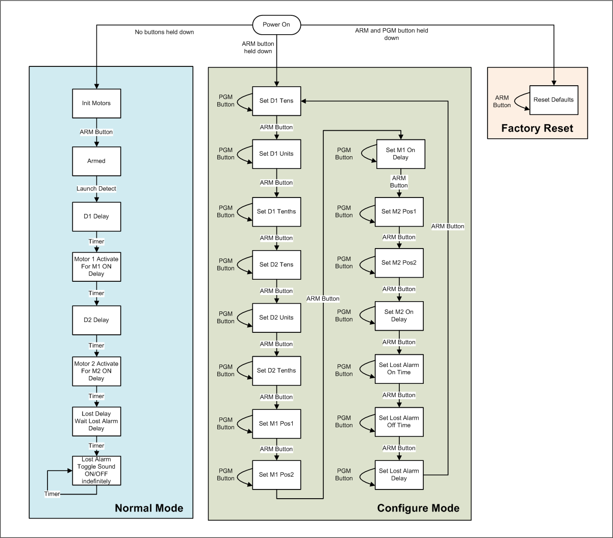
Figure 1 shows the flow diagram for the three modes. Each mode will
be discussed in more detail
below.
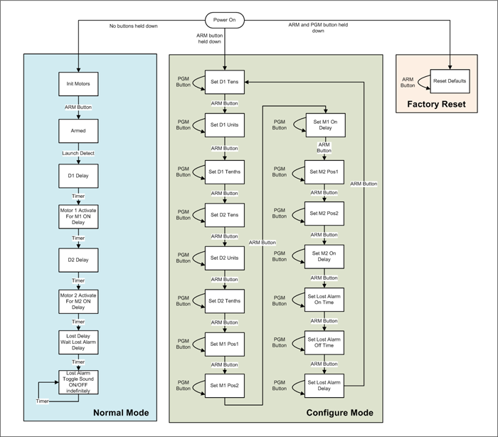
Figure 1
- Operational Mode -
Flow Diagram
Video describing the operation of the FC.
When this period expires the FC
goes to the next phase.
- M1 On Time
� At the end of D1
servomotor M1 moves from position 1 to position 2. The
amount of time it spends doing that is set through the
M1 On Time parameter. The servo remains in this
position until power is turned off and turned
back on again. This is the time
that a parachute or the next stage is released.
Display shows:

At the completion of the servo
repositioning the FC enters the D2 phase.
- D2
� The FC waits a second period of
time before the second servomotor is activated.
Display shows:

At the conclusion of the D2 delay the FC
switches to the next phase.
- M2 On Time �
Servo M2 moves from
position 1 to position 2. The amount of time it spends
doing that is set through the M2 On Time
parameter. The servo remains in this position until
power is turned off and turned back on
again.
Display shows:

When the motor
finishes moving the FC switches to the lost delay phase.
- Lost Delay �
If enabled, the FC waits for another period of time
before starting the lost rocket alarm. Typically the
rocket is found by the time the alarm sounds and power
is turned off. The period can be set from 0 minutes to
31 minutes.
Display shows:

- Lost Alarm �
When the Lost Delay period expires, the alarm
starts sounding and continues indefinitely until either
power is turned off or the batteries run flat.
Display shows:

Flight Profiles
Following are
examples of a few
different flight profiles that can be configured with the FC.
Please refer to the examples section for more details on
these:
- Single stage
with launch detect or burnout detect
- Two stage �
Staging and main parachute with launch detect
or burnout detect
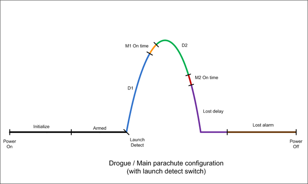
- Dual Parachute
(Drogue/Main) with launch detect
or burnout detect
Configure Mode
In the configure mode the user can
cycle through all parameters and change their values.
All values are automatically and permanently stored in the EEPROM. Table 1
describes each of the parameters and the range of values
that can be set for each. Table 2
describes the values themselves. To avoid confusion a
parameter name on the display is designated with a �.�
(decimal point) and the parameter's value
does not have the decimal point.
Since the values can range from 0 to 31,
alpha-numeric
characters (0 � 9, and A � V) are used to display all
values.
To enter configure
mode and change the parameters do the following:
- Make sure power
is OFF.
- Hold down only
the ARM button and turn the power
ON.
The �S�
 symbol appears on the display indicating you are
in �Set� or configure mode
symbol appears on the display indicating you are
in �Set� or configure mode
- Press the ARM
button repeatedly to cycle through the parameters.
- Press the PGM
button repeatedly to cycle through the parameter values.
- When finished
changing the parameters switch the power OFF.
|
Parameterer |
Mnemonic |
Default |
Range |
Display
|
Description
|
|
D1
Tens |
D1Tens |
0 |
[0 �
9] |
 |
Represents the number of 10's
of seconds to wait in the D1 delay. |
|
D1
Units |
D1Units |
3 |
[0� 9] |
 |
Represents the number of seconds to wait in the D1
delay. |
|
D1
Tenths |
D1Tenths |
5 |
[0� 9] |
 |
Represents the number of 0.1 seconds to wait in the
D1 delay. |
|
D2
Tens |
D2Tens |
0 |
[0� 9] |
 |
Represents the number of 10's
of seconds to wait in the D2 delay. |
|
D2
Units |
D2Units |
5 |
[0� 9] |
 |
Represents the number of seconds to wait in the D2
delay. |
|
D2
Tenths |
D2Tenths |
0 |
[0� 9] |
 |
Represents the number of 0.1 seconds to wait in the
D2 delay. |
|
M1 Position
1 |
M1P1 |
0 |
[0� V] |
 |
Motor 1
Position 1. (prior to launch) |
|
M1 Position
2 |
M1P2 |
V |
[0� V] |
 |
Motor 1
Position 2 (after delay D1) |
|
M1 On Time |
M1On |
F
(2.4 sec) |
[0� V] |
 |
0.16 sec /
step |
|
M2 Position
1 |
M2P1 |
0 |
[0� V] |
 |
Motor 2
Position 1 (prior to launch) |
|
M2 Position
2 |
M2P2 |
V |
[0� V] |
 |
Motor 2
Position 2 (after delay D2) |
|
M2 On Time |
M2On |
F
(2.4 sec) |
[0� V] |
 |
0.16 sec /
step |
|
Lost On Time |
LOn |
1 |
[0� V] |
 |
How long the buzzer sounds
0.25 sec /
step |
|
Lost Off
Time |
LOff |
4 |
[0� V] |
 |
How long the buzzer is silent
0.25 sec /
step |
|
Lost Delay |
LDly |
5
(5min) |
[0� V] |
 |
How long before the alarm
sounds
minute /
step
|
Table 1
- Configurable Parameters
|
Value |
Index |
Displayed as
|
|
Value |
Index |
Displayed as
|
|
Value |
Index |
Displayed as
|
|
0 |
0 |
 |
|
B |
11 |
 |
|
M |
22 |
 |
|
1 |
1 |
 |
|
C |
12 |
 |
|
N |
23 |
 |
|
2 |
2 |
 |
|
D |
13 |
 |
|
O |
24 |
 |
|
3 |
3 |
 |
|
E |
14 |
 |
|
P |
25 |
 |
|
4 |
4 |
 |
|
F |
15 |
 |
|
Q |
26 |
 |
|
5 |
5 |
 |
|
G |
16 |
 |
|
R |
27 |
 |
|
6 |
6 |
 |
|
H |
17 |
 |
|
S |
28 |
|
|
7 |
7 |
 |
|
I |
18 |
 |
|
T |
29 |
 |
|
8 |
8 |
 |
|
J |
19 |
 |
|
U |
30 |
 |
|
9 |
9 |
 |
|
K |
20 |
 |
|
V |
31 |
 |
|
A |
10 |
 |
|
L |
21 |
 |
|
|
|
|
Table 2
- Parameter Values
Functionality
Timing
The two main timing delays D1 and D2
are configured through 3 parameters each. Both D1 and D2 are configured in the
same way.
Timing Periods
Table 3
lists the minimum and maximum values that each specific
phase can be configured to.
|
Delay |
Min |
Max |
|
D1 |
0.1 sec |
99.9 seconds |
|
M1On |
0.16 sec |
5.12 seconds |
|
D2 |
0.1 sec |
99.9 seconds |
|
M2On |
0.16 sec |
5.12 seconds |
|
Lost
Delay |
0 minutes |
32 minutes |
Table 3
- Delay Ranges
Each of the servomotors has two
configurable positions Position 1 and Position 2.
Position 1 is the position prior to launch. This
would typically be the latched position of the recovery
system. Position 2 is the position of the servomotor
after the expiry of the appropriate period. The motors
remain at their Position 2 position until power is
turned off.
RC servomotors are positioned using a
specific pulse train on their control line. The FC generates
this pulse train for only a short period of time determined
by the M1 On Time or M2 On Time parameters.
This allows battery power to be conserved when the motors
are not required to move. The On Time should be
adjusted in such a way that the motor has enough time to
move from one position to the other. Sometimes this needs to
be adjusted depending on the motor used or if there is a
load on the motor and it takes longer.
The full range of movement of each
servo is divided into 32 steps. This means a servomotor that
normally has a 90 degree range of movement will be able to
be positioned with an accuracy of 2.8 degrees, while a servo
that has a 200 degree range of movement can be positioned
with an accuracy of 6.25 degrees.
The positions are made configurable to
allow the servomotors to be mounted inside the deployment
system in any orientation. Sometimes clockwise operation is
needed and sometime anti-clockwise is required.
The positions can also be adjusted
between flights in the Configure Mode if something
becomes misaligned or stretched in the deployment system and
the servomotor positions need to be updated to compensate.
HINT:
When configuring the motor positions, set the M1 or M2
On Time delays to something like "6" this will
allow you to reposition the servo motors faster as you cycle
through their positions. Don't forget to go back and set the
appropriate time delay when you are finished.
The FC can use the built in buzzer to
sound an alarm after a delay to assist the rocketeer to locate
the rocket if it is lost in tall grass or hanging in
a tree.
There are 3 configuration settings
associated with the alarm. The first is the number of
minutes it takes before the alarm is activated (Lost
Delay). This is useful for two reasons. Firstly it
allows the FC to conserve the battery since in most
instances the rocket will be found before the alarm needs to
sound. Secondly it allows the FC to remain quiet in flight
when used in combination with a video camera that is also
recording audio.
The other two parameters are used to
configure the sound duration during the alarm phase. Setting
the Lost On Time to a short beep and the Lost Off
Time to a long period allows the FC to conserve power,
but for more noisy environments the alarm can be set to
produce noise more frequently at the expense of power
consumption.
Setting the All three
parameters to
zero allows the lost alarm functionality to be switched off
altogether.
Most of the fun only happens after the
FC is triggered from the Armed phase. Triggering can be
achieved a number of different ways depending on the rocket
design. Some examples include:
- Launch
detect � This is typically
achieved using a G or acceleration switch. Triggering
occurs as soon as the rocket leaves the launch pad.
Another variation to this is a set of contacts that are
closed and an insulator is removed from between them
during launch. The insulator is usually attached so it
stays with the launcher.
- Burnout
detect - This technique
uses a pressure switch to detect when the pressure
inside the rocket has reached atmospheric pressure, or
some preset value. This is useful for staging rockets.
This allows the rocket to deploy the second stage at the
correct time regardless of how much pressure or water
was used in the booster.
- Negative G
detect � This is another
technique used to detect when the rocket has stopped
producing thrust and the rocket starts to slow down. An
inverted mercury switch can be used here where the
mercury floats upwards to make contact as drag continues
to slow the rocket down after burnout. Negative Gs
happen shortly after burnout.
We�ll leave it up to the rocket
builder to come up with their own way to trigger the FC. The
FC can have a G-switch fitted directly to the PCB, but the
FC also provides a connector for external triggers inputs.
Following are a number of examples
demonstrating how to configure the FC for various scenarios.
You want to use a single parachute on
a simple rocket. You want the parachute to deploy at 3.5 seconds.You also don�t want
to use the lost alarm functionality. You will also be using
the built in G-switch.
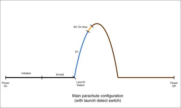
Figure 3 - Simple rocket with single
parachute scenario
This is how you would configure the
computer:
Enter the Configure mode by holding the ARM button down
while turning the power ON. Use the ARM button to advance
through the parameters, and the PGM button to advance
through the values.
Motor M1 is set for full range
movement by setting �6.� to "0" and �7.� to
"V".
If the servo was to move in the other direction the two
values would be reversed. The servomotor will be on for 2.4
seconds. This is set by parameter �8.� (value = 2.4 /
0.16 = 15 = F)
We set the �C. D. and E.� parameters to 0
to turn off the lost alarm.
|
|
D1 |
D2 |
M1 |
|
D1Tens |
D1Units |
D1Tenths |
D2Tens |
D2Units |
D2Tenths |
M1P1 |
M1P2 |
M1On |
Param
|
|
|
|
|
|
|
|
|
|
|
Value |
00 sec |
|
0.5 sec |
|
|
|
0 |
32 |
2.4sec |
|
|
|
|
M2 |
Lost |
|
|
M2P1 |
M2P2 |
M2On |
LOn |
LOff |
LDly |
|
|
Param |
|
|
|
|
|
|
|
Value |
|
|
|
|
|
|
When finished setting the parameters,
turn the power OFF.
Now if the rocket
will fly with the same setup on every launch, all you have
to do for each launch is turn on the FC and press the ARM
button and the rocket is ready to go. This makes it
very simple to use once configured.
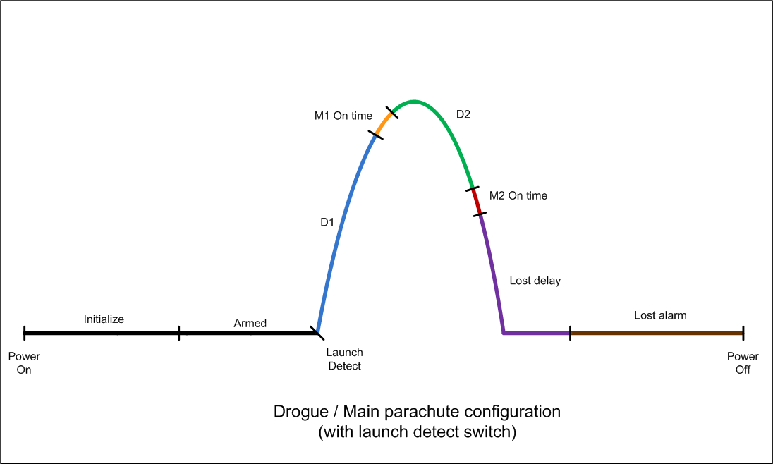
Say you have a more advance rocket
that will deploy a drogue parachute at apogee and then
the main parachute some time later when it has had a chance
to descend some way. This technique is often employed to
prevent large parachutes from being opened at high speeds as
well as to stop the rocket drifting too far in windy
conditions.
You also want to use the lost alarm
functionality as you are flying in wooded terrain.
A simulation of the rocket predicts
that it will reach apogee after 7.25 seconds.
Using drogue parachute descent rate
calculations you decide that the main parachute should
deploy 22 seconds after apogee.
This is how you would configure the
computer:
Set D1 and D2
Since the timing resolution is only in 0.1 second
increments we set the first delay to say 7.3 seconds. D2
will be set to 22 seconds. (see table below)
Set M1 and M2
Because of the deployment system
configuration we need to set the M1 servomotor to turn
clockwise and the M2 servomotor to turn anticlockwise when
activated. We set the positions as appropriate for the
deployment system. In this example they are just set to full
range. The On Time for both servos only requires
~1 second.
See the values in the table below.
Because the Motor On Time is set in increments of 0.16
seconds, we find that the closest value to 1 second is 0.96
seconds = 0.96/0.16 = 6. So we set the value to "6"
for parameters "8." and "b.".
Set Lost Alarm
We choose to set the alarm for 5
minutes after main parachute deployment, and we want the
sound to beep for 1 second and stay quiet for 3 seconds.
Parameter �E.� sets the delay in minutes, so we set
it to 5. The sound on time and off time are given in
0.25second increments so we set �C.� to 4 (1sec/0.25
= 4) and the �d.� parameter to C (3sec/0.25 = 12 = C)
|
|
D1 |
D2 |
M1 |
|
D1Tens |
D1Units |
D1Tenths |
D2Tens |
D2Units |
D2Tenths |
M1P1 |
M1P2 |
M1On |
Param
|
|
|
|
|
|
|
|
|
|
|
Value |
00 sec
|
|
0.3 sec |
20 sec |
2 sec |
0.0 sec |
0 |
32 |
.96sec |
|
|
|
|
M2 |
Lost |
|
|
M2P1 |
M2P2 |
M2On |
LOn |
LOff |
Ldly |
|
|
Param |
|
|
|
|
|
|
|
Value |
32 |
0 |
.96 |
1 sec |
3 sec |
5 min |
When finished setting the parameters, turn the power OFF.
Now if the rocket will fly with the
same setup on every launch, all you have to do for each
launch is turn on the FC and press the ARM button and
the rocket is ready to go.
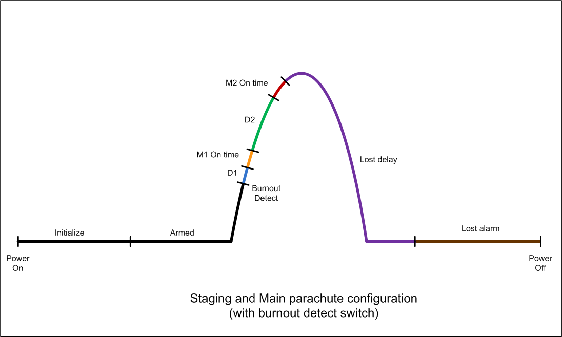
In this scenario the FC is fitted to
the booster of a 2-stage rocket and will be used for
initiating the staging of the next stage and some time later
for opening a parachute on the booster. The ideal time to
release an upper stage is when the booster is travelling at
its fastest which happens right around burnout. It is also
the worst time to deploy a parachute since it could be
ripped off.
The external trigger this time is
based on a pressure switch that activates when the pressure
inside the rocket drops to 10psi above atmospheric pressure.
This means that a short time later the rocket will be
travelling the fastest as the pressure drops to 0.

This is how you would configure the
FC:
Let�s assume that the time between the
sensing of the pressure drop to the time that the second
stage should be released is only
0.2s. We need to set the
D1
delay to 0.2
seconds. This means parameters "0." and "1."
are set to "0" and parameter "2." is set to "2".
M1 and M2 positions and
Motor On Times are
configured as in the previous example. And the lost alarm
functionality is turned off.
In this example we set the delay to
parachute opening to be 2 seconds after staging. We
set the "3." parameter to "0" and the "4."
parameter to "2". The "5." parameter is set to
"0".
|
|
D1 |
D2 |
M1 |
|
D1Tens |
D1Units |
D1Tenths |
D2Tens |
D2Units |
D2Tenths |
M1P1 |
M1P2 |
M1On |
Param
|
|
|
|
|
|
|
|
|
|
|
Value |
00
sec |
|
0.2 sec |
00
sec |
2 sec |
0.0 sec |
|
|
0.96sec |
|
|
|
|
M2 |
Lost |
|
|
M2P1 |
M2P2 |
M2On |
LOn |
LOff |
LDly |
|
|
Param |
|
|
|
|
|
|
|
Value |
|
|
0.96 sec |
|
|
|
When finished setting the parameters, turn the power OFF.
Now if the rocket will fly with the
same setup on every launch, all you have to do for each
launch is turn on the FC and press the ARM button and
the rocket is ready to go.
To reset the configurable parameters
back to the default factory settings do the following:
- Make sure the power
is OFF.
- Hold the PGM and ARM buttons down
at the same time and turn the power ON.
- The �r�
character will be
displayed. Followed by the decimal point.
- Press the ARM button once more to
confirm the reset. And the decimal point will
disappear.
- After the beep, turn the power
OFF.
The default factory settings are set
up for a typical single stage 2L water rocket.
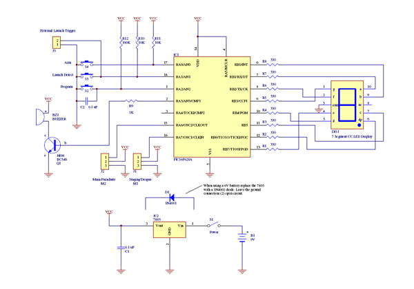
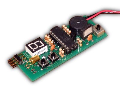
Hardware
The circuit diagram for version 1.6 is
shown in Figure 4. Central to
the design is the PIC16F628A microcontroller from Microchip.
The on-board oscillator is used to reduce the external
component count.