last updated: 21st october 2023 - Day 226 to Day 230 - Various Experiments

Safety First

Search

Site Index

Tutorials

Articles

Rocket Gallery

Labs

Where To Buy

10 Challenges

Links

Blog

Glossary

Contact Us

About


Construction - Basic

Body

Ring Fins

Flat Fins

Nozzle

Nosecone

Construction - Advanced

Robinson Coupling

Splicing Bottles #1

Splicing Bottles AS#5

Reinforcing Bottles

Side Deploy #1

Side Deploy #2

Mk3 Staging Mechanism

Multi-stage Parachutes

Fairings

Construction - Launchers

Gardena Launcher

Clark Cable-tie

Medium Launcher

Cluster Launcher

Launch Abort Valve

Quick Launcher

How It Works

Drop Away Boosters

Katz Stager Mk2.

Katz Stager Mk3.

DetMech

Dark Shadow Deployment

Articles

Recovery Guide

Parachutes

How Much Water?

Flying Higher

Flying Straight

Building a Launcher

Using Scuba Tanks

Nozzles

Video Taping Tips

MD-80 clone

Making Panoramas

Procedures

Burst Testing

Filling

Launching

Recovery

Electronics

Servo Timer II

V1.6

V1.5

V1.4

V1.3, V1.3.1, V1.3.2

V1.2

Deploy Timer 1.1

Project Builds

The Shadow

Shadow II

Inverter

Polaron G2

Dark Shadow

L1ght Shadow

Flight Log Updates

#230 - Tajfun 2 L2

#229 - Mac Uni AON

#228 - Tajfun 2 Elec.

#227 - Zip Line

#226 - DIY Barometer

#225 - Air Pressure Exp.

#224 - Tajfun 2

#221 - Horizon Deploy

#215 - Deployable Boom

#205 - Tall Tripod

#204 - Horizon Deploy

#203 - Thunda 2

#202 - Horizon Launcher

#201 - Flour Rockets

#197 - Dark Shadow II

#196 - Coming Soon

#195 - 3D Printed Rocket

#194 - TP Roll Drop

#193 - Coming Soon

#192 - Stager Tests

#191 - Horizon

#190 - Polaron G3

#189 - Casual Flights

#188 - Skittles Part #2

#187 - Skittles Part #1

#186 - Level 1 HPR

#185 - Liquids in Zero-G

#184 - More Axion G6

#183 - Axion G6

#182 - Casual Flights

#181 - Acoustic Apogee 2

#180 - Light Shadow

#179 - Stratologger

#178 - Acoustic Apogee 1

#177 - Reefing Chutes

#176 - 10 Years

#175 - NSWRA Events

#174 - Mullaley Launch

#173 - Oobleck Rocket

#172 - Coming Soon

#171 - Measuring Altitude

#170 - How Much Water?

#169 - Windy

#168 - Casual Flights 2

#167 - Casual Flights

#166 - Dark Shadow II

#165 - Liquid Density 2

#164 - Liquid Density 1

#163 - Channel 7 News

#162 - Axion and Polaron

#161 - Fog and Boom

#1 to #160 (Updates)


WATER ROCKET - FLIGHT COMPUTER
This section describes the details of the water rocket flight computer (FC) as designed by the Air Command team.

The purpose of the FC is to co-ordinate various events during the flight of a water rocket. One of its responsibilities is to deploy the parachute at the desired time.

Version 1.4
The circuit diagram.
FC V1.4 mounted inside the Acceleron IIIb payload pod.


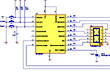
Version 1.4 of the flight computer extends the functionality of V1.3.1. It has been designed specifically to work with a booster in a two stage rocket. It controls two RC servo actuators. One releases the staging mechanism and the other to deploys the parachute. The computer also does not use a launch detect switch, instead it uses a pressure switch that detects when burnout has occurred.

The flight computer is powered by a 9V battery that is stepped down to 6V. This allows the power supply to be replaced by a lighter 6V battery when needed.

To date V1.4 has flown 5 times. (updated 29th March 2008 - includes day 57)

Operation

Initially when the computer is turned on, it sets the two servos to their default closed positions.

The user then can select the length of a delay that will be used to delay the parachute deployment after staging has occurred. This delay allows the booster to wait until the second stage has had enough time to clear away from the booster, and the booster has had enough time to slow down near apogee so that parachute deployment is less violent.

The minimum time that can be set after staging is 2 seconds, that's because the staging servo is sent pulses for 2 seconds for it to operate. Pressing the "Program" button repeatedly cycles through the time delay values.

The allowed delays can be set in quarter second increments as follows:

LED Display Deploy Delay after staging
(Seconds)
0 2
1 2.25
2 2.5
3 2.75
4 3
5 3.25
6 3.5
7 3.75
8 4
9 4.25
A 4.5
b 4.75
C 5
d 5.25
E 5.5
F 5.75
G 6
h 6.25
i 6.5
J 6.75
k 7
L 7.25
m 7.5
n 7.75
o 8
P 8.25
q 8.5
r 8.75
S 9
t 9.25
U 9.5
v 9.75
w 10

After the delay is set the the rocket needs to be pressurised in order for the pressure switch to deactivate. Once sufficient pressure has been supplied to the rocket. The system can be armed by pressing the "Arm" button.

The FC now waits until the pressure switch activates. When burn-out is detected a quarter of a second later the staging servo activates to release the second stage.

The FC then waits the chosen delay and activates the parachute deploy servo. After the parachute has been deployed the FC returns both servos to their default positions.

Software

The assembly source code can be found here: Flight1_4.asm

The assembled HEX code can be found here: Flight1_4.HEX


Copyright © 2006-2023 Air Command Water Rockets

Total page hits since 1 Aug 2006: