The Servo Timer II was primarily designed for parachute
deployment on water rockets, but can be used for other
applications. The timer controls a single RC servo motor
that can open a latch on a parachute door. Once triggered
the timer waits a set amount of time before moving the servo
motor. The timer has a number of configurable parameters
along with several trigger options. It may also be used in
other applications such as staging rockets, controlling
camera direction etc.
Servo Timer II
Features
6 - 9V operation
Single RC servo output - Can drive most common RC
servo motors.
Configurable servo start and end positions
0-12 second delay selectable in 1 second increments
Built in 2G acceleration switch for launch detect
External make or break wire trigger
External 3V - 12V hi/low trigger
External timer output
High-brightness 'ARMED' status LED visible in broad
daylight from 50 feet.
Timers can be cascaded
ICSP connector for firmware updates
Weight: 6 grams
Dimensions: 25mm x 43mm (1 x 1.7 inches) - Fits in
T8 FTC.
Also a thank you goes to the water rocket community who
have supported us over the years and given us feedback on
the previous versions of this timer. We have taken your
suggestions and incorporated them into this design.
Buy It Now -
SOLD OUT
Updated: 26th May 2013 - Sorry but there are no more Servo Timer IIs
left for
sale, as they have all sold out. Thank you to everyone who has purchased the timer. We
will continue to provide support for the timers. If you have
any
questions or comments please contact us.
If you would like to build your own, the STII PCB layout
(in Eagle .brd format) and .HEX files are now available for
FREE on request. All the SMD
components can be substituted with through-hole components
to make it easier to build on a prototyping board. (Sorry we
don't have a through-hole PCB layout)
The section at the end of this article
covers
hints and tipson how to use
this timer.
Triggering the timer
The timer can be triggered in a variety of ways depending
on the application.
Built in G-switch: The built in G-switch will detect a
launch when the timer experiences acceleration of over 2G.
Depending on the application, such as when triggering occurs
at burnout or apogee, or
where the board cannot be oriented vertically, the built in
G-switch trigger option can be disabled.
Break wire: A pair of contacts is available on the input
connector to connect a loop of wire. Depending on the
configuration, either a break in the loop will trigger the
timer, or connecting the loop will trigger it. This allows
the timer to be triggered by simple mechanical contacts or
switches whose contacts are normally open or closed.
External higher acceleration G-switches can also be directly
connected to this input. Pressure switches used for
detecting burnout may also be connected.
External 3-12V input signal: This input is routed through
an opto-coupler isolating the timer from the triggering
circuitry. This allows other circuits and flight computers
operating on different power supplies to trigger the timer
directly without additional circuitry.
This input can usually be connected directly to a pyro
output of a flight computer or altimeter.
The timer can be started by a variety of events depending
on the application. Some trigger event examples include:
Launch
detect � This is typically
achieved using a G or acceleration switch. Triggering
occurs as soon as the rocket leaves the launch pad.
Another variation to this is a set of contacts that are
closed and an insulator is removed from between them
during launch. The insulator is usually attached
to the launcher.
Burnout
detect - This technique
can use a pressure switch to detect when the pressure
inside the rocket has reached atmospheric pressure, or
some preset value. This is useful for staging rockets.
This allows the rocket to deploy the second stage at the
correct time regardless of how much pressure or water
was used in the booster.
Negative G
detect � This is another
technique used to detect when the rocket has stopped
producing thrust and the rocket starts to slow down. An
inverted mercury switch can be used here where the
mercury floats upwards to make contact as drag continues
to slow the rocket down after burnout. Negative Gs
happen shortly after burnout.
We�ll leave it up to the rocket
builder to come up with their own ways to trigger the
timer.
Configuration
Before using the timer in an application for the first
time it needs to have the trigger condition and servo motor
start and end positions configured.
Configuring the Trigger condition
To change the timer's trigger condition, do the
following:
With the power
OFF set the rotary switch to the "D"
position.
Turn the timer ON.
The
LED should flash 3 times.
Now rotate the switch to one of
the following settings:
Setting
Description
0
Internal G-switch
1
External trigger on Make wire
2
External trigger on Break wire
3
Opto-coupler input trigger on High
4
Opto-coupler input trigger on Low
5
Internal G-switch with manual
ARM
NOTE: See the Connections
section for wiring details of each of the trigger
conditions,
Turn the timer OFF.
The value is automatically saved in
the internal EEPROM. The next time the timer is turned on it
will be configured with the new trigger condition.
Configuring Servo Positions
In normal operation when the timer is first turned ON the
servo motor moves to the start position. When the timer
expires, the servo motor moves to the end position.
Due to the large variety of RC servo motors available,
and because there are numerous situations in which they can
be used it is possible to set the start and end position of
the servo. Up to 16 positions are possible over the range of
movement of the servo motor. The timer produces timing from
~0.7ms to 2.4ms which should cover most RC servo motors.
A servo that has 180 degrees of travel can be positioned
in ~11 degree increments, while a servo with 90 degrees of
travel can be positioned in ~5 degree increments.
Configuring Servo Start Position
With the power OFF, turn the switch to the "F" position.
Turn the timer ON
The LED will flash once.
The servo motor will be positioned to the currently set
start position. If you want to retain this position, turn the
timer OFF.
If you wish to change the position, turn the switch
slowly to one of the 16 settings until the motor reaches the desired position. The
setting will be automatically stored in the EEPROM.
Switch the timer OFF. The new setting will be ready when
the timer is turned back on.
NOTE: You should turn the switch to one of the 0-C
positions after setting the motor position so that you don't
accidentally enter the configuration change when the timer is
powered on next time.
Configuring Servo End Position
With the power OFF, turn the switch to the "E" position.
Turn the timer ON
The LED will flash 2 times.
The servo motor will be positioned to the currently set
end position. If you want to retain this position, turn the
timer OFF.
If you wish to change the position, turn the switch
slowly to one of the 16 settings until the motor reaches the desired position. The
setting will be automatically stored in the EEPROM.
Switch the timer OFF. The new setting will be ready when
the timer is turned back on.
NOTE: You should turn the switch to one of the 0-C
positions after setting the motor position so that you don't
accidentally enter the configuration change when the timer is
powered on next time.
Normal Operation
With the power OFF, set the timer to the desired
time delay
on the rotary switch: 0-C (0-12seconds). Note that when
the switch is set in the D-F range when powering on the
timer will enter configuration mode.
Setting the timer to 0 delay, allows the timer to be used
with other apogee detecting sensors such as the uMAD or a
barometric altimeter, so that the servo is activated as soon
as apogee is detected.
Zero delay is also useful when the timer is used with burn-out detection sensors for activating a staging mechanism in
multi-stage rockets.
Turn the power ON.
The servo motor will move to the
start position.
NOTE: You can then turn the timer off again
at this point. This is useful for getting the motor set in
the correct position when setting up the deployment
mechanism in the stowed position.
After 5 seconds the timer enters the ARMED state and
the LED will light. In this state the timer starts
monitoring the configured trigger condition. If you have
chosen trigger option 5 with manual arm, you need to
first close the contacts to arm the timer.
When the trigger condition is met, the timer starts
the delay.
At the end of the delay, the servo motor is moved to
the END position activating the deployment mechanism. The
timer also outputs a high signal on the external output
pin 4 on the JP2 connector and brings it low again at the
end of the motor movement. You can use this output to
drive external circuits.
The timer then briefly flashes the LED every few
seconds to remind you to turn the power off. We killed a
couple of batteries during development when we forgot to
turn off the power.
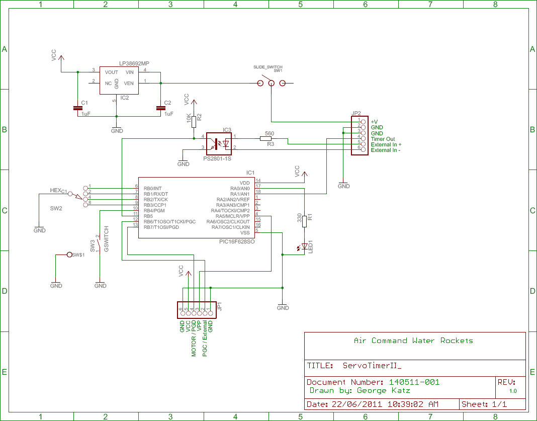
The circuit diagram for the
servo timer II is
shown in Figure 1. Central to
the design is the PIC16F628A microcontroller.
The on-board oscillator is used to reduce the external
component count.
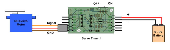
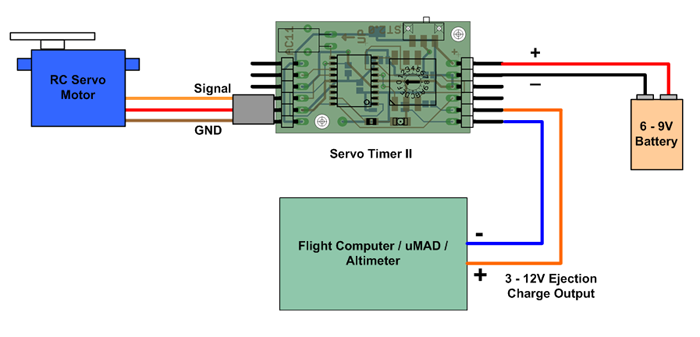
The timer only needs a battery and an RC servo
motor for the standard configuration. The timer comes standard
with a 9V battery clip, but you can connect your own batteries
to the timer.
Figure 4. - Standard connection
Trigger Options
The following diagrams show the different wiring
connections needed for each type of trigger option. See the
Configure trigger section for
configuring the trigger option.
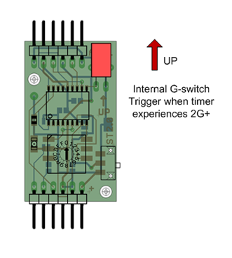
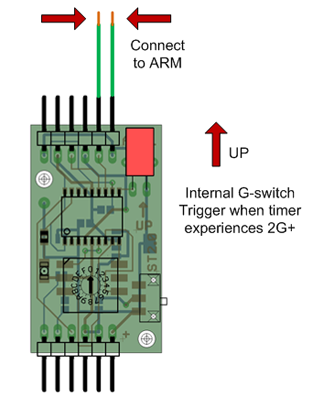
Trigger Option 0 - Internal G-switch
No external wiring is necessary for this option.
The internal G-switch (shown in red) will trigger the timer when
it undergoes acceleration of greater than 2G. A false trigger
filter is implemented by the timer so small shocks should not
cause the timer to activate. If you experience false triggers
with your rocket configuration consider using some of the other
trigger options such as trigger option 5..
IMPORTANT NOTES:
The timer must be oriented
vertically for the G-switch to trigger.
If you are launching a rocket with a small
nozzle and at low pressure the acceleration may be too low
to trigger the timer using the internal G-switch. In this
case we suggest using trigger option 1 or 2 to trigger the
timer on launch.
Figure 5. - Trigger Option 0
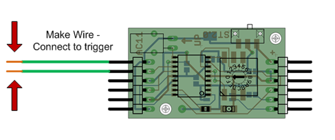
Trigger Option 1 - External trigger on Make wire
Connecting pins 1 and 2 on the JP1 connector
will cause the timer to trigger. You can connect any mechanical
type contacts to these pins.
Figure 6. Trigger Option 1
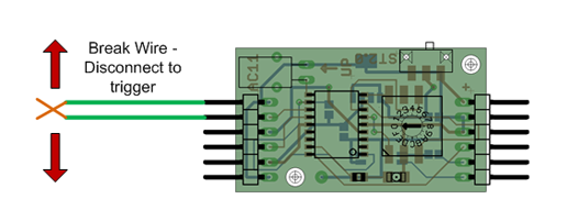
Trigger Option 2 - External trigger on Break wire
Disconnecting pins 1 and 2 on the JP1
connector will cause the timer to trigger.
Figure 7. Trigger Option 2
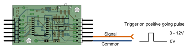
Trigger Option 3 - Opto-coupler input trigger on High
A positive going pulse on pin 5 of the JP2
connector will cause the timer to trigger. You can connect the
output of a flight computer, altimeter, uMAD or other powered
sensors directly to this input. These include the pyro outputs
from most rocket electronics.
Figure 8. - Trigger Option 3
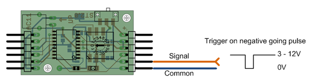
Trigger Option 4 - Opto-coupler input trigger on Low
A negative going pulse on pin 5 of the JP2
connector will cause the timer to trigger.
Figure 9. - Trigger Option 4
Trigger Option 5 - Internal G-switch trigger with manual ARM
This trigger option allows manual arming of the
timer. The internal G-switch is used to detect launch, but the
timer is only armed once pins 1 and 2 of JP1 are connected.
Normally the timer self arms 5 seconds after power-on. This
allows the timer to be armed remotely if the process of
pressurising the rocket is causing false triggers, or you need
an extra secure trigger.
IMPORTANT NOTES:
The timer must be oriented
vertically for the G-switch to trigger.
If you are launching a rocket with a small
nozzle and at low pressure the acceleration may be too low
to trigger the timer using the internal G-switch. In this
case we suggest using trigger option 1 or 2 to trigger the
timer on launch.
Figure 10. - Trigger Option 5
External Trigger
The servo timer can be directly triggered by
other flight computers, altimeters or apogee detectors. The
easiest way to connect the timer is to use the pyro ejection
charge output on those devices. This trigger input is opto-coupler
isolated so you can run the flight computers from a higher or
lower voltage than the timer. The input is TTL compatible.
Figure 11. Triggering from external devices
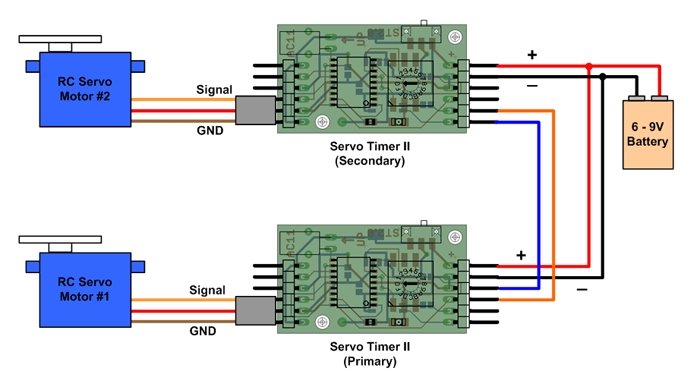
Cascading Timers
If you need to control two separate servo
motors to do two different functions you can cascade the
timers so that one triggers the other. You can connect both
timers to the same battery, but keep in mind that if you are
driving both servo motors simultaneously, the battery needs
to have the capacity to do so.
Connect the Timer output (pin 4 on JP2) from
the first timer to the External Trigger input+ (pin 5 JP2)
of the second timer. Connect the ground wire (pin 3 on JP2)
from the first timer to the External Trigger input- (pin 6
on JP2) on the second timer.
Now configure both timers as described
above.
The external output signal of the first
timer activates at the same time that the servo motor is
activated. If you set a 0 delay on the second timer then
both servo motors will move simultaneously.
You can cascade as many timers as will fit
in your rocket.
Figure 12. Cascading Timers
Servo Motors
Standardand micro RC servomotors can
be used with the servo timer and are available from most
hobby stores. E-bay also has sets of servo motors at
reasonable prices. The typical weight of the
micro servos is anywhere from
3g to
15g, although larger ones can be used but you must ensure
that the battery can
deliver the higher currents. The timer supports currents
of up to 1A for brief periods.
Power Supply
The servo timer can be powered by
any DC voltage source in the 6V to 9V
range. This includes 6V
batteries, which can be made up of something like 2xCR123A's or
4x AAAA etc. a 9V battery, or a 2S LiPo battery pack at 7.4V.
etc.
Power Consumption
The
servo timer when armed and awaiting launch consumes
~10mA + servo standby power of around 6mA. When driving small servo motors, the current is likely to reach
around 100-300mA. With a large stalled servo motor it could
reach ~1A. This power is only applied
for about 1second. After servo activation the timer + servo
draws about 7.5mA.
Notes
IMPORTANT:
When using the
on-board G-switch, you need to ensure that the PCB is
oriented vertically and the G-switch is pointing up. If
the PCB is not oriented this way, the servo timer most
likely will
not trigger.
If you are launching rockets with small nozzles and low
pressures then the rocket's acceleration may be too low to
trigger the timer using the internal G-switch. In that case
you can use the other trigger options to start the timer.
You need to factor in that the
deployment time is not the same as the parachute open time.
It may take one or two seconds before the parachute is fully
open, so if you are aiming for opening your parachute right
at apogee, you need to start deploying it a little earlier. How much
time it takes to fully open the parachute depends on the
design of the deployment system, the parachute type and the
parachute packing technique.
Estimates for time delay
settings is
easiest done with a water rocket simulator that can predict
the trajectory of the rocket.
Adjustments to the timing can be
easily achieved on subsequent flights.
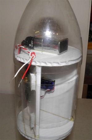
Example of Servo Timer II used for
parachute deployment
Servo Timer II used in conjunction with a
uMAD for parachute deployment
Hints and Tips
This section will cover some tips on how to use the timers in
deployment mechanisms and other applications.
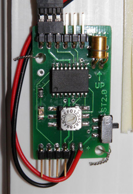
You can use regular machine screws to mount the timer to your
deployment mechanism, but over the years we have found that
during a crash the screws can put quite a bit of stress on the
PCB and break it. We now almost always use just single core wire
and thread it through the mounting holes and twist it. This
holds the timer securely but during a crash it has some give.
The wire ties will also save you a little bit of weight. For
extra security you can use double sided tape under the timer and
then tie it down with the wire.
Timer attached with wire ties.
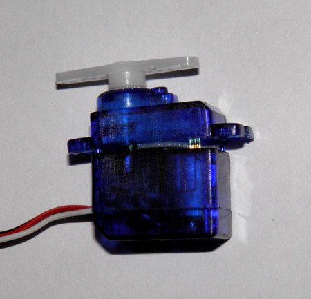
Tip 2: Look out for dodgy servos
10th July 2011
When buying inexpensive servos take a look to see how they are
assembled. The case normally comes in three parts. The cheaper
variety tend to be just pressed together with little tabs. Under
high G-loads the servo can fall apart and fail as shown in the
photo below:
Some servos can fall apart under high G-loads.
This is particularly an issue when they are mounted vertically
in the deployment mechanism. Hard impacts can also cause them to
come apart. If you rough up the sides and epoxy a couple of
pieces of plastic on both sides and make sure that all three
sections are joined together then you can use the servos without
issues.
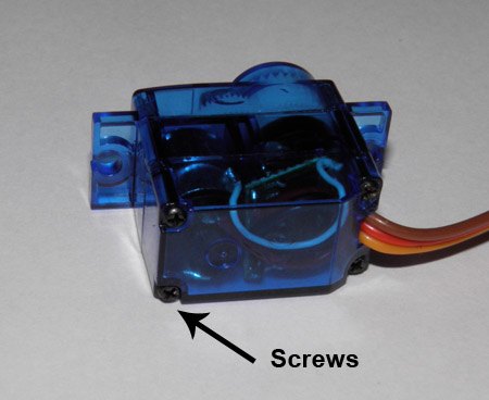
Better still find servos that have screws that hold the three
sections together as shown below:
Better servos have the case screwed together.
Tip 3: Mounting a micro servo motor
10th July 2011
Depending on your deployment mechanism you will need to mount
your servo motor somewhere. We used to use the
servo to pull a pin
on the release mechanism, but the main draw back was that you
needed to have a servo powerful enough to overcome the friction
of the pin in the latch. This was particularly an issue if the
parachute ejection spring was putting a large force on the
latched door. Since then we have switched to using the servo to
simply let go of a rubber band holding the door. This allows you
to use even the smallest sub micro servos to release a parachute
door, as the pulling force is in the direction the servo is
moving. In this arrangement the servo is mounted centered around
the door.
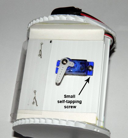
We simply cut a hole in the Coreflute for the motor to just
slide in and secure it with a small self tapping screw. These
often come with the servo motors. You can use a couple of screws
if you like.
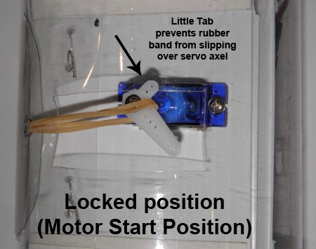
NOTE: Leave a little tab on the servo horn to prevent the
rubber band from slipping over the servo axel. Without this tab
it is possible that the rubber band will get caught on the servo
horn. The following sequence shows how the servo releases the
door.
The rubber band holds the parachute door closed.
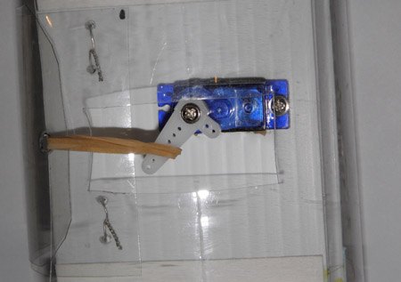
As the servo starts moving the little tab pushes the rubber band
to one side.
The rubber band slides down the servo horn.
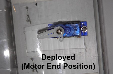
Until it completely slips off opening the door and deploying the
parachute.
With the super tiny sub-micro servos you want to get the rubber
band as close to the axel as possible while in the stowed
position as the rubber band can exert a high enough torque on
the servo horn to turn it by itself. You can also turn the servo
horn so the start position is such that it points almost all the
way around and then half the rubber band goes over the little
tab and under the big arm. This spreads the torque either side
of the axel and will not turn it. When the motor starts moving
it will swing the rubber band over and release the parachute.
Tip 4: Using the timer to deploy a parachute
8th September 2011
Here is a full tutorial on how
to use the timer to deploy a parachute on a water rocket.
Tip 5: Simple Break-wire launch
detect trigger
25th November 2011
If you are going to attempt fairly slow launches such as
restricted nozzles, or foam you can use the break-wire option on
the timer. All you need is a simple connector and two wires. You
can buy these from a store, but if you have an old computer or
other piece of electronic equipment that you are about to throw
out, look inside, as often the front LEDs, speaker, buttons etc.
are often connected to the mother board with one of these.
Just snip it off and strip the ends - about 1
cm. You can tin them if you like but it's not necessary. You can
just twist the strands together.
Make a knot in the wires about 2-3 cm from the stripped ends.
This will stop the wires from pulling out during launch.
Program the timer for Trigger
Option 2 and connect the connector to pins 1 and 2 on JP1.
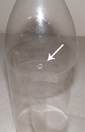
Make a small hole in the fairing, just big
enough for the two wires to fit and thread them through.
The knot should prevent them from coming out any further.
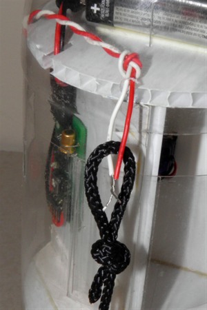
Securely attach one end of a piece of string to the launcher,
and tie a loop in the other end. Thread the loop of string onto
one of the wires and then twist them together about 1.5 times.
Turn on the timer and wait for it to arm. When the rocket
launches, the loop will pull through and break the wire
connection triggering the timer. The break only needs to happen
momentarily to trigger the timer. It does not matter that the
wires touch afterwards.
Make sure you test the setup a couple of times before your
first launch.
NOTE: Don't twist the wires too many times otherwise you may
rip the nosecone off the rocket. :)
Disclaimer
In no respect shall Air Command Water Rockets incur any
liability for any damages, including, but limited to,
direct, indirect, special, or consequential damages arising
out of, resulting from, or any way connected to the use of
the item, whether or not based upon warranty, contract,
tort, or otherwise; whether or not injury was sustained by
persons or property or otherwise; and whether or not loss
was sustained from, or arose out of, the results of, the
item, or any services that may be provided by Air Command
Water Rockets.
While we try to ensure the quality of the Servo Timer II,
we cannot guarantee a rocket's safe return to Earth since
the timer is fitted in recovery systems beyond our
control. This product should always be considered experimental.