 |
 |
![]()
![]()
![]()
|
|
last updated: 3rd May 2026 - Day 245 - Launch Tubes #3 |
|
|
|
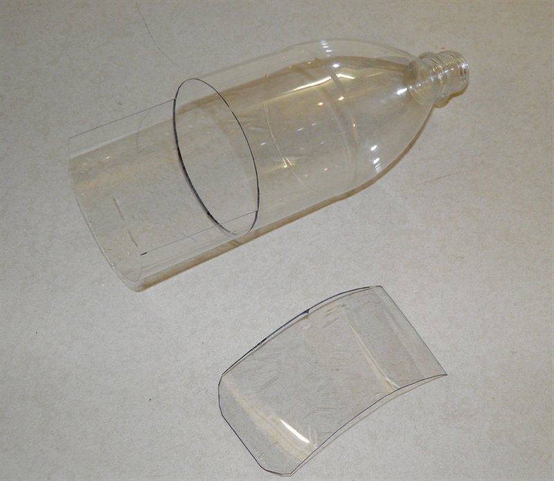
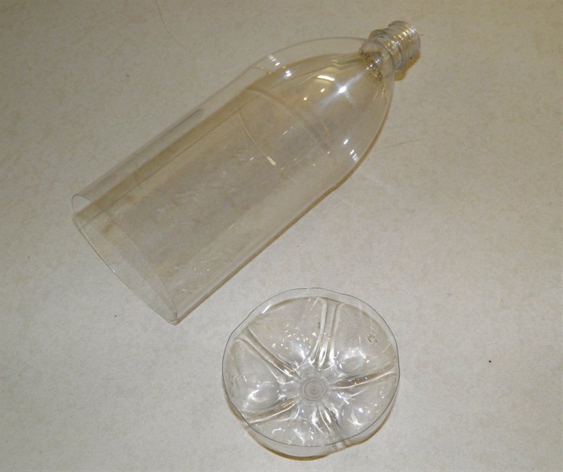
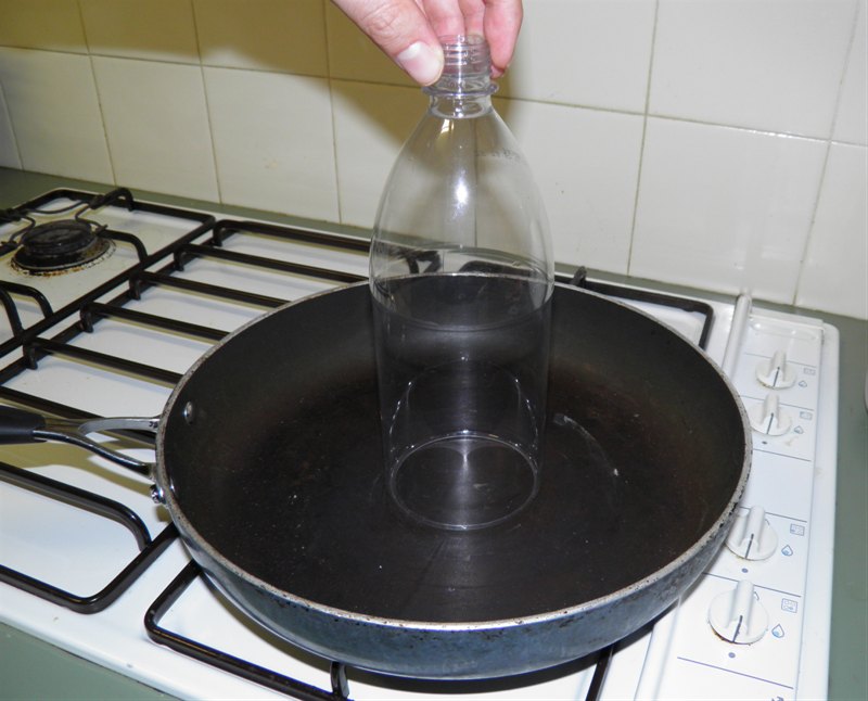
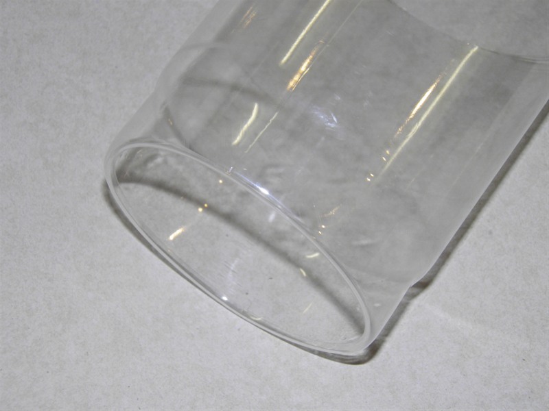
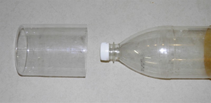
Splicing Bottles AS#5 |
|
#235 - Coming Soon |
|
#234 - Coming Soon |
|
#233 - Coming Soon |
|
#232 - Coming Soon |
|
#196 - Coming Soon |
|
#193 - Coming Soon |
|
#172 - Coming Soon |
|
|
|

|
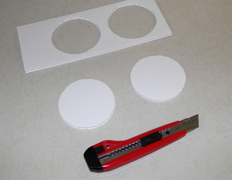
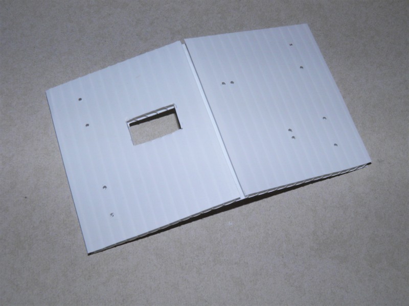
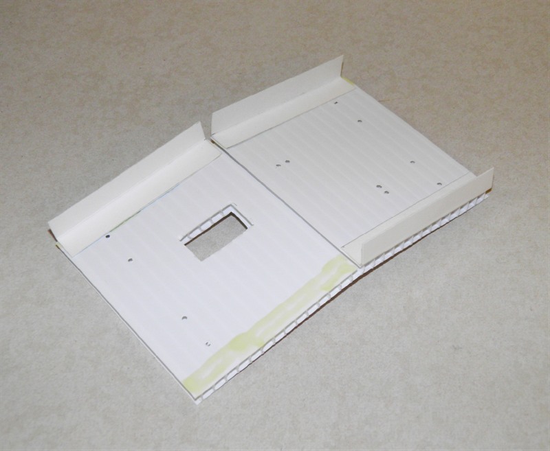

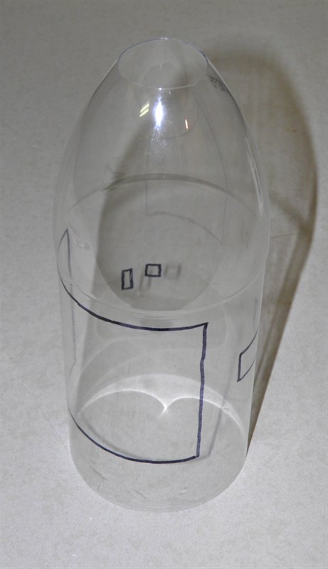
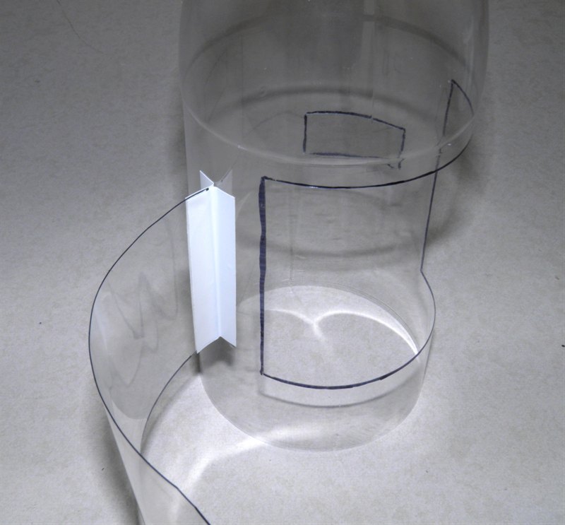
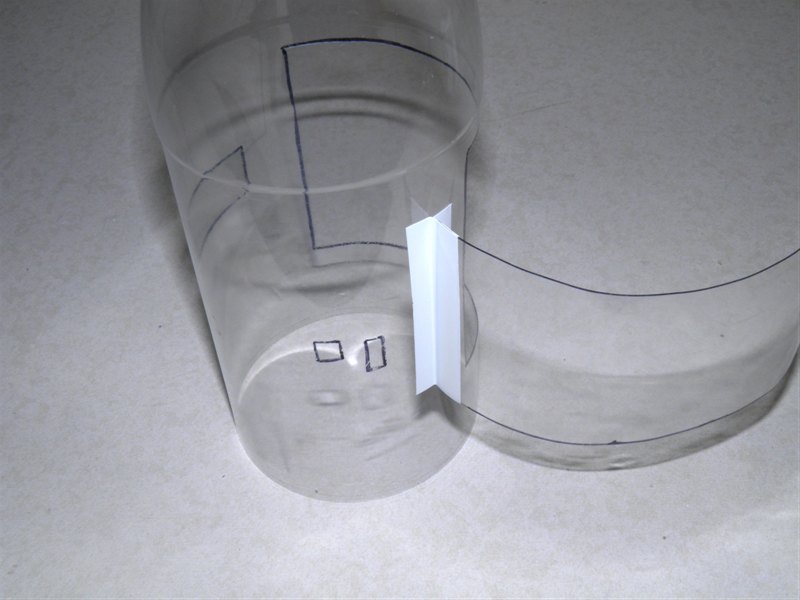
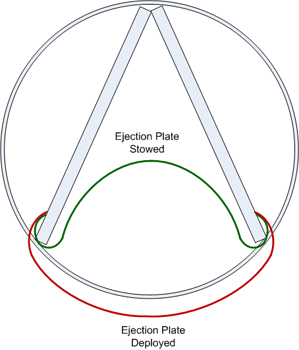 Using
a felt marker, mark out the hole for the parachute. The hole should be a
little wider ~3mm than the two sides of the V. This
allows space for the ejection plate to flex. Vertically
the hole should be just smaller than the inside edges of
the circles.
Using
a felt marker, mark out the hole for the parachute. The hole should be a
little wider ~3mm than the two sides of the V. This
allows space for the ejection plate to flex. Vertically
the hole should be just smaller than the inside edges of
the circles.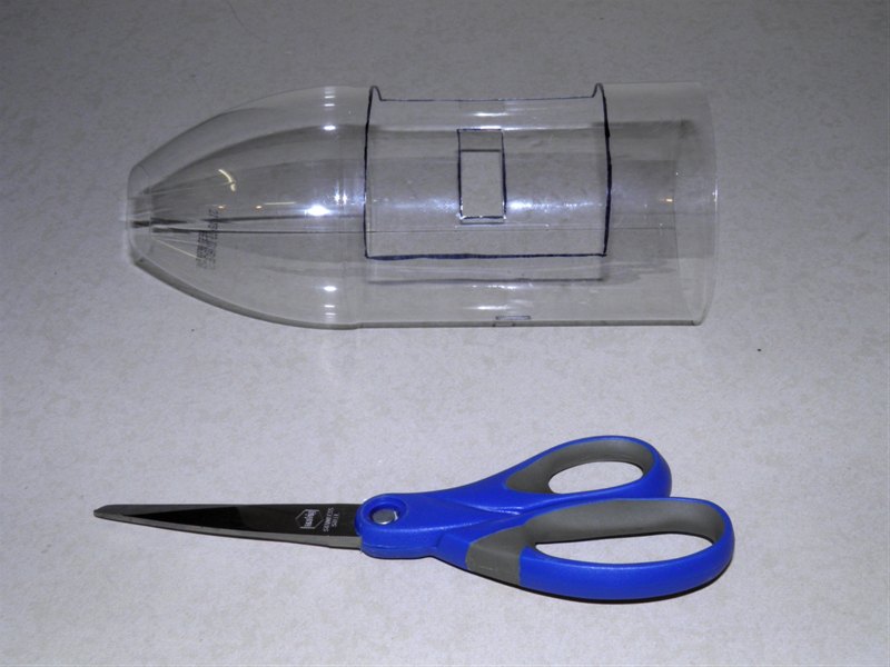


Back to Top Construction Index