Each flight log entry usually
represents a launch or test day, and describes the
events that took place.
Click on an image to view a larger image, and
click the
browser's BACK button to return back to the
page.
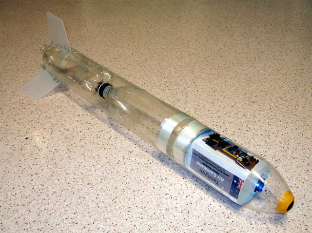
Day 37 -
Tachyon Sustainer
The new Tachyon sustainer. It will likely
get painted a dark colour so we can see it
against the sky.
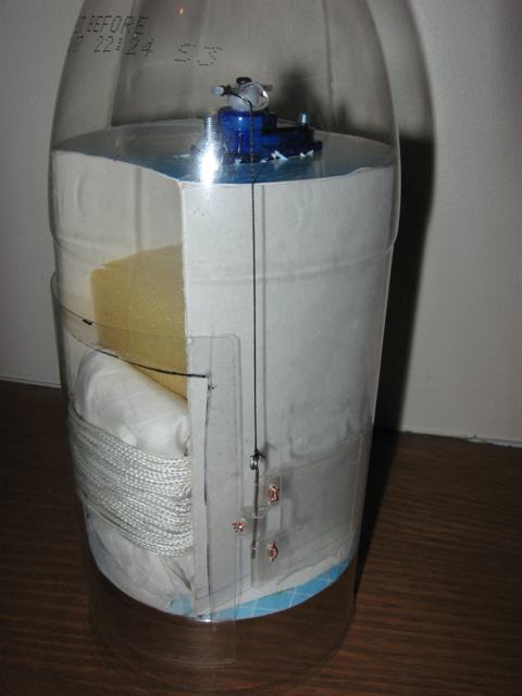
The deployment mechanism is removable for
easier access. The ring on the left holds it in
place.
Detail showing the RC servo and the thread
going to the pin. The parachute is pressed
against the door by the soft foam.
Diagram of the
sustainer showing the arrangement of the various
components.
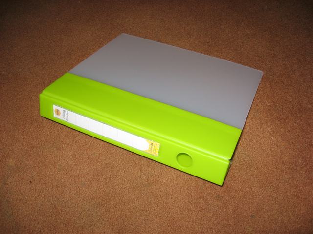
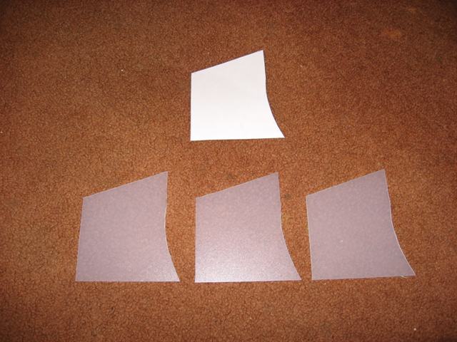
The folder the fins are made from.
Template and the cut out fins.
Diagram of
the removable fin assembly used by the Tachyon
sustainer.
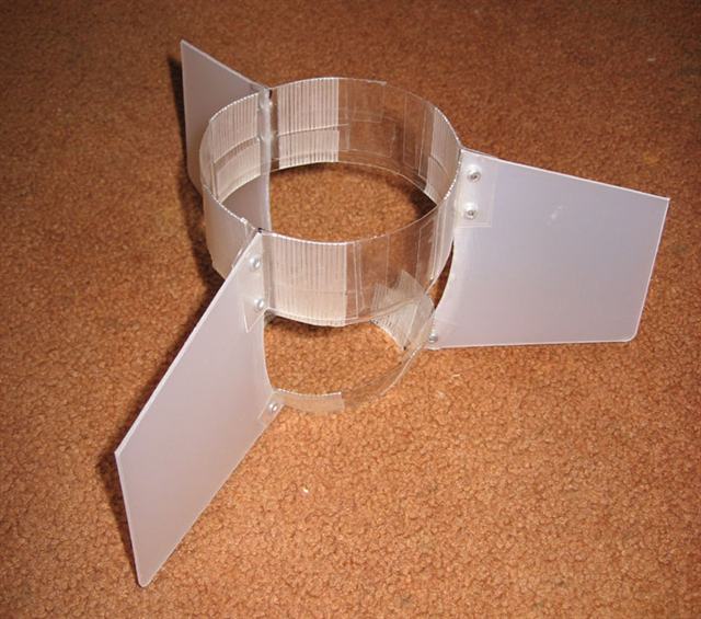
The fin assembly.
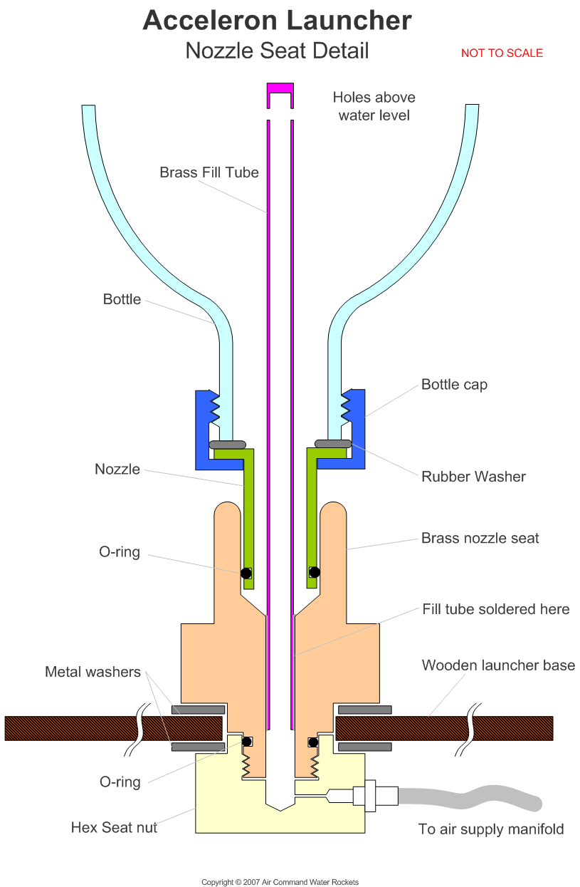
Details
of the Acceleron launcher nozzle seat.
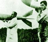
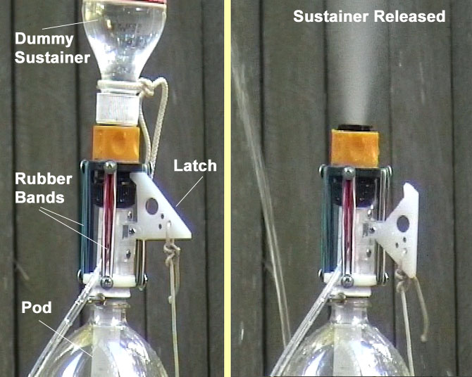
Before and after shots of the sustainer
staging mechanism
Date:13th
June
2007
Location: Workshop
Conditions: Pleasant
since it was indoors.
Rockets:
(click the name for rocket details)
A new rocket designed
specifically as a sustainer to work
with the Acceleron III booster.
Team Members at
Event:
GK and PK
Development
We continue to develop our multistage
rocket, but we had to have a chuckle today,
as it is just turning out to be much more
complicated than what we initially
anticipated. When we did a full component count
today, we found that there are close to 300
individual components for the
booster alone. (not counting all the pieces of
tape)
We are going to pursue
with our approach, but in the future we will
simplify the design. In any case it will be
fun to see when it finally gets off the
ground. There is just something to be
said about the simplicity of a crushing
sleeve mechanism.
Tachyon
We finished the Tachyon sustainer this
week. That means we now have final flight
hardware that we can mate to the booster.
There are a number of new functional and construction techniques used on this rocket
that we haven't tried before:
Nosecone shape - The tip of the
nosecone is round, and is simply made by
gluing half a ping-pong ball to the hole
left after removing the bottle throat.
The curvature fits well to make a clean
aerodynamic shape
Sideways opening hinged door - The
parachute hatch door hinge is parallel to
the rocket axis. The door itself provides
a clean aerodynamic cover.
Soft sponge for chute ejection - We
are trying a simple approach for providing
the force to eject a parachute. No need
for rubber bands, pistons, springs and the
like. This is a single component solution
that is inexpensive, lightweight and can
be reused, should the rocket crash.
Simple pin pulling mechanism - The pin
that opens the door is attached to a piece of thread, and the other is
tied directly to the RC servo horn.
RC micro-servo actuator - We decided
to go with this slightly heavier option,
but it comes in a nice neat package, it is
easily mountable, powerful, and the
position can be set directly by the flight
computer. These cost us $6.50 delivered.
Removable fin assembly - The fin
assembly is now made so that it can be
attached to the lowest bottle without any
tape, glue or rubber bands. This allows us
to swap the fin assembly on the rocket in
the field, should it become damaged during
landing.
5 mm nozzle - The nozzle is newly
machined to conform to the standard 9mm
Gardena mechanism, but the internal hole
is only 5mm. This allows us to use a
7mm or 9mm nozzle for testing the sustainer by itself, and
the 5mm one for boosted flight.
Tachyon uses
V1.3.1 of the flight computer to deploy
the single 42 cm parachute. We are using a 9V
battery to power it, so that we get plenty
of current capacity while we are doing
tests. If we ever end up going for any
records, we can replace the battery with a
much lighter one to gain those few feet. The
9V battery just makes it much more
convenient, because they are cheap, and
available everywhere.
The deployment mechanism is also now
removable from the nosecone. This allows us
much easier access in assembling all the
components. All the components are mounted
on cardboard bulkheads. The entire deploy
mechanism is held in place with a piece of
curled bottle which provides enough support
for the G forces that the rocket is likely
to encounter. Mounting the payload section
this way allowed us to produce a much more
streamlined nosecone and payload section.
The Acceleron III pod bulkheads are made
from corrugated plastic used to make signs.
Removable fin assembly
We first tried gluing the fins directly
to the PET bottle with PL Premium, but we
found that the plastic we chose for the fins
did not stick to PL Premium at all even with
careful cleaning and sanding. The glue
held great to the bottle though. Instead of
choosing a different fin material ( we liked
it's rigid yet non-brittle properties ) we
decided to make a self contained fin
assembly that could be removed.
The fin material itself came from the
cover of a folder bought at OfficeWorks. The
plastic is translucent, quite rigid, but not
brittle. You can cut it with scissors.
To each fin are attached four L-brackets
made from a 2L juice PET bottle plastic.
This plastic is much thicker than regular
PET bottle plastic. These L-brackets are
attached with aluminium pop rivets to the
fins instead of glue. The pop rivets are
hammered flat on both sides to make them
more aerodynamic. These L-brackets are then
simply taped with glass-fibre reinforcing
tape to two PET plastic rings that fit the
profile of the bottle.
The upper ring is made from a larger
bottle and heat shrunk to fit exactly the
profile of the rocket body. The lower tapered ring
is simply a section of another bottle, and
because of its conical shape it does not
need to be shrunk.
The reason the fin arrangement does not
need to be taped to the rocket body is
because of the little lip that exists at the
base of the curved section of the bottle.
(refer to diagram). When you are putting the
assembly on, you have to distort the bottle
(collapse it inward) in order to slide the
tight fitting upper ring over the lip. Once
over the lip the bottle can spring back to
its original shape. The tapered lower ring
prevents the fin assembly from moving up the
bottle, and the lip prevents it from moving
back. It is impossible to remove the
assembly without distorting the bottle
again. This way you can swap the fin
assembly in less than a minute should you
need to.
Testing
We assembled the staging mechanism
release trigger and tested it under
pressure. At first it turned out that the
rubber bands just weren't providing enough
pulling force when pressurised (you were
right Trevor). When there
was no pressure the coupling released just
fine. We added a few more rubber bands and
it worked a treat.
For the tests we were only pulling on the release
mechanism with a string. The next step is to
have the servo release the trigger. But for
that we need to complete V1.4 of the flight
computer. The actual cable going to the
servo is made out of Tiger Tail - a strong
and very thin steel cable coated with nylon.
It is used for making necklaces.
We have also had a number of requests for
details of the Acceleron launcher, so we
have included a cross section detail showing
the the nozzle seat and how air is supplied
to the booster.
A couple of days ago was our first
vertical launch anniversary. We would like
to thank all the people in the water rocket
community for contributing their ideas to
make this a really enjoyable hobby.