Date: 27th May
2007
Location: Workshop
Conditions: Pleasant
since it was indoors.
Rockets:
(click the name for rocket details)
|
Name |
Capacity |
Notes |
|
Acceleron III |
24.75
L |
A new rocket expanding on
Acceleron II's capacity. It is also our first
two stage rocket booster. |
Team Members at
Event:
GK and PK
Development
Although we haven't done an update for a
while we have still been busy developing the
Acceleron III booster and its staging
mechanism.
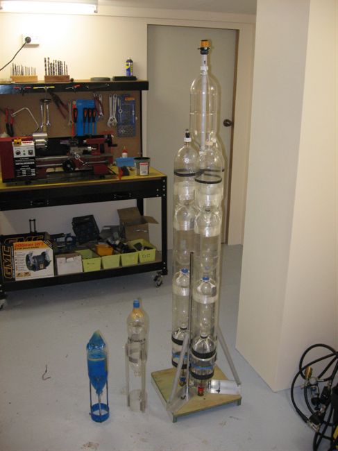
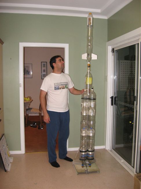
Design
The Acceleron III booster has 3 segments
each with a capacity of 8.25L. The booster
segments are attached to a central aluminium
tube running the full length of the rocket.
Each booster has a 10mm nozzle. The full
details of the rocket design including
dimensions will be published once the rocket
is finished. We are changing the design as
we build it so to do the drawings too early
would be a waste of time.
The Payload Pod
All the electronics, actuators, camera
and parachute will now be mounted inside a pod
that sits just above the three booster
segments. The pod provides protection for
those components from the sustainer spray
during release and during landing.
The pod has a PVC pipe running through it
to support the sustainer. There are two RC
servo actuators inside the pod. One is used
to deploy the parachute, and the other is
used to release the second stage. The servos
will be controlled by version 1.4 of the flight
computer.
The bulkheads in the pod are made from
corrugated plastic sheets used to make
signs. We decided to go with this material
because it is relatively stiff, lightweight,
water proof and cheap to obtain. The
bulkheads are just glued together with a
polyurethane glue.
The pod's aeroshell also provides a
stabilising anchor point for the sustainer
during ascent.
New software is currently under
development to support
the staging mechanism and parachute
deployment sequence.
Staging Mechanism
The staging mechanism is based on a
Gardena hose attachment. We removed the
spring from it and glued a plastic ring on
the outside sleeve. Rubber bands are
attached to this ring to provide the pulling
force needed to release it. A small latch
keeps the sleeve in place and this latch
will be
controlled by a servo motor inside the pod.
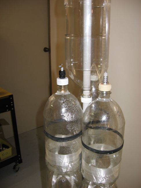
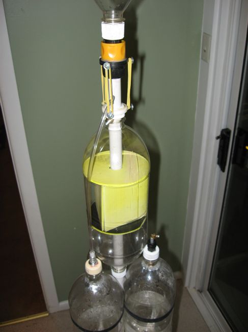
Sustainer Air Supply
The air supply to the second stage feeds
through a thin clear plastic hose from
the top of one booster segment. The hose is
attached to a unit that has a swivel
connector as well as a non-return valve in
it. The swivel connector is useful for when
we remove the cap to fill the segment with
water.
We cut off the regular garden hose
attachment on the Gardena fitting and glued
in an adaptor for the thin hose. The hose
passes out of the central tube just above
the pod to allow us to remove the pod from
the tube for maintenance.
Parachute Deploy
The parachute bay now uses a piece of soft
spongy foam to help push the parachute out
when the door opens. We decided to go with a
sideways opening door this time because it
made the parachute bay more streamlined. The
hinge is made from a piece of cloth. The
door latch is quite simple (and it uses a flexible
line
to unhook it. The line directly connects to
the servo motor.
Staging and parachute deploy sequence
The second stage release timing will be
initiated by a device known as a TDD. This
was kindly donated by Trevor. It is
based on a pneumatic piston inside a
cylinder that activates when the pressure
inside the rocket drops below a certain
pressure. The TDD is connected to a
micro-switch that then connects to the
flight computer. When the pressure drop is
detected a small delay later the second
stage is released. The flight computer then
starts a second delay, and when that delay
is over the parachute is deployed.
Sustainer
The Tachyon sustainer is a new rocket
being designed to fit the Acceleron III
booster. It is made from two 1.25L bottles
joined together with a Robinson Coupling. It
will
use a 5mm nozzle (our smallest yet). The
fins are not complete yet, the ones in the
photo are only representative. Tachyon uses
version 1.3 flight computer for parachute
deployment. For now the deploy delay is time
based.
Pressure Testing
We have now completed our pressure tests
for all the different components up to 125
psi. (Except the sustainer).
Thanks to the new bigger lids, the three
booster segments held up well without leaks
up to the maximum test pressure.
We also tested the seal around the TDD.
Although up to about 40 psi there was a
small leak around the piston, above 40 psi
it started sealing properly and went well
all the way up to max pressure without
problems. Just doing crude tests, the TDD
activated in the 10psi range which is pretty
good.
After we assembled the sustainer's air
supply we tested it for leaks, and it leaked
a little bit. Upon closer inspection we
found on the inside of the thin tube that
there are three ridges running the full
length of it. This is probably the main
reason it leaked around where it attaches.
We made new rings for the outside that were
a much tighter fit and it then it held fine
up to the maximum test pressure.
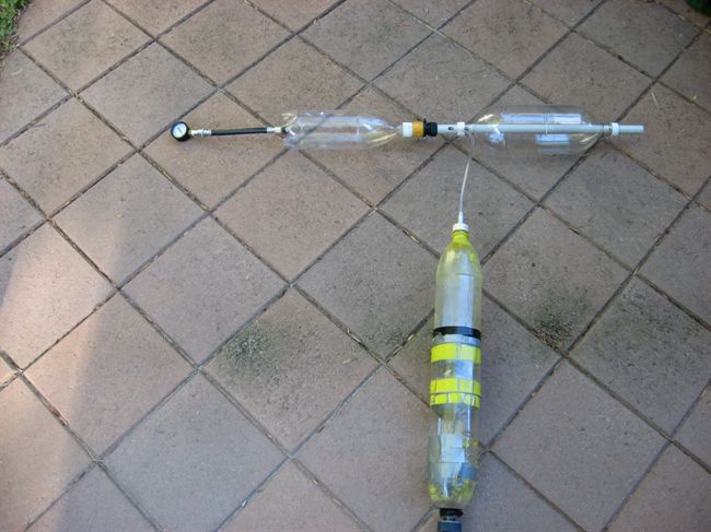
We made a special connector for the top
of a bottle that could connect a pressure
gauge using a quick release fitting. We put
this in place of the sustainer and we
performed a test of the non return valve at
the end of the thin tube. Using the attached
pressure gauge we could see that the valve
held the pressure in the sustainer just fine
for the minute or two that we observed it.
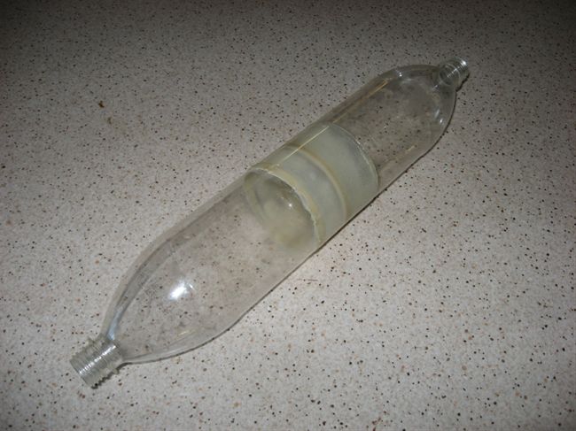
Other Developments
We also had a go at splicing our first
bottles. We used some PL premium kindly
donated by Jordan from
Team Parental
Advisory. We decided to splice them base to
base so to speak so that these units can
screw together to make longer rockets or be
replaced should they get damaged. Thanks
also to
Damo for advice on splicing. We still
need to burst test these. More info on this
next time.
Ben Jackson is also working on similar
projects with flight computers for water
rockets. Here is his deployment system:
http://www.youtube.com/watch?v=nf3tDq_kbZQ
Another recent and interesting deployment
system from Christian Thomsen is here:
http://ph.groups.yahoo.com/group/water-rockets/photos/browse/a9d3
It is still going to be at least a couple
of weeks before we get a chance to fly this
multistage rocket. |