|
Date: 21st September 2008
Location:
Workshop
Conditions:
Pleasant
Team Members at Event:
GK and PK
Test Stand Work
Over the past few weeks we have
been building a sensitive test stand on
which we will be able to test design ideas
and see how they affect performance.
The
last test stand we built was not
sensitive enough to measure the differences
we are interested in. The new stand is based on a single point load-cell
connected to a load cell amplifier and the
amplifier in turn is connected to a data logger.
The guys on the
Forum for Australian Rocketry
were a great help in recommending which
equipment to use, things to look out for,
and generally how to set it up.
Big thanks
goes to Tarp,
PK, PatchleAD, astroboy and others who helped
us get the right
parts and steer us in the right direction. Load Cell
Load cells tend to be quite
expensive, easily upwards of $150-200+. We
had been researching a lot of different
companies and finally found a new 70kg load
cell from a
Chinese manufacturer whose cost
and delivery were far cheaper than local
distributors. We ended up paying
US$24 for it
+ $9 delivery. Delivery was around 8 days.
We chose the 70Kg load cell as it was a good
compromise between the upper and lower
ranges of thrust we want to explore. Data Logger
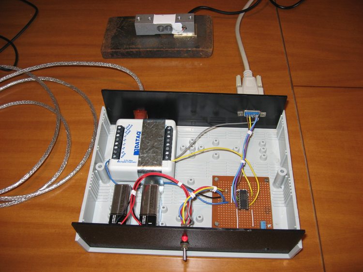
The data logger we chose was from DATAQ.
We went with the
DI-148U as it already had a
USB connection. My laptop doesn't have a
serial port so I would have needed a serial-to-USB converter anyway. If it did have a
serial port we probably would have gone with
the cheaper
DI-194RS.
We ordered the logger from a local
distributor called
Total Turnkey Solutions (www.turnkey-solutions.com.au).
All up delivered the DI-148U Starter Kit was AU$118. I was very impressed with the
delivery time.
I placed my order just before lunch on
Thursday
and the package from Melbourne was waiting
for me on Friday when I got home from work. Load Cell
Amplifier
The data logger and load cell aren't
enough though, and we also need a load cell
amplifier. The data logger reads in
the -10V to 10V range with a 10-bit accuracy. The load cell only
produces millivolts over the entire
deflection range which is too low for the
data logger to get enough resolution. The
amplifier basically converts these small
voltage changes to a voltage over the full
dynamic range of
the logger. It also provides the necessary
excitation voltage for the load cell.
You can buy these off-the-shelf but you will
pay upwards of $100. Being on a limited
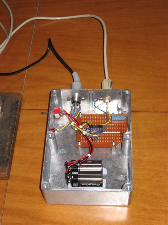
budget, we decided to build our own. The
amplifier is based on an
instrument amplifier IC
INA125P. The circuit is
relatively straight forward and these IC's
are designed for exactly this task.
Because it is not easily sourced within Australia, we
ordered them from Texas Instruments in the
US. Circuit Diagram
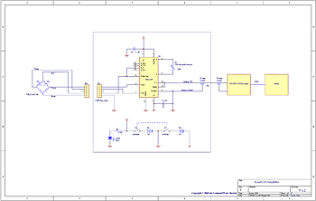 You can adjust the
amplifier's gain using the multi-turn trim
pot in order to get the
required thrust range. Because we use
two 9V
batteries as the power source we don't quite
get the full +/-10V range, but it is close
enough. The excitation voltage used for the
load cell is 5V. Parts List
Since this was going to be a one-off we
didn't bother with a PCB and just built the
circuit on a strip board.
|
Part |
Designation |
Quantity |
Source |
|
INA 125P Instrument Amp |
U1 |
1 |
Texas
Instruments |
|
16 Pin IC socket |
- |
1 |
Jaycar |
|
50 ohm
Coax Connector |
JP2 |
1 |
Jaycar |
| 5
DIN socket |
JP1 |
1 |
Jaycar |
|
DPDT switch |
S1 |
1 |
Jaycar |
|
Power LED |
LED1 |
1 |
Jaycar |
|
500 Ohm multi turn pot |
R1 |
1 |
Jaycar |
|
1.5KOhm |
R2 |
1 |
Jaycar |
|
0.1uF Capacitor |
C1, C2 |
2 |
Jaycar |
|
9V battery |
B1,B2 |
2 |
Jaycar |
|
9V battery clip |
- |
2 |
Jaycar |
|
Metal enclosure |
- |
1 |
Jaycar |
Software
The data logger came with free "lite"
software for capturing and viewing the data.
However, being free there are some
limitations in terms of exporting the data
and maximum allowed sample rate. The max
sample rate is 240Hz which is more than
ample for us. The full software with higher
allowed sample rates (14,400 samples/sec) is another $200. You
can also buy a $99 software add-on that lets
you save the captured data into Excel
friendly format. (*doh*) The free software, however, does record the
data into their own proprietary binary file
format. I recorded a number of waveforms, and looked at the data in a hex
editor. The data was not encrypted,
so it was relatively easy to
reverse-engineer its format and write a
small program that now allows me to convert their
format into a text .csv file format that is
directly readable by Excel. (saved $99 there
:) )
Preliminary Testing
After initial testing it was discovered
that there was a little bit of noise on the
signal which allowed measurements down to
about 20 grams. One of the guys (PK) on the
Forum for Australian Rocketry made some good suggestions
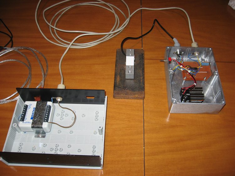
about how to reduce the signal noise. I
ended up placing the load cell amplifier close to the load
cell and enclosed the whole thing in a metal
box. I also used a coax cable to run the long
lead to the data logger. The noise level
dropped off dramatically. It is now down to
around 0.02V over the -9V to 9V range.
On the 70Kg load cell that allowed me to
resolve down to ~5 grams = a sheet of A4
paper. (Yes I actually put a sheet of
paper on it). This means we can get thrust
measurement accuracy down to about 0.05
Newtons. This hopefully should be good
enough to observe the subtle changes to
components under test. The expected thrust range
of most rockets under test will be about
30N to 150N. That range applies for our
typical rockets with pressures of around
120psi with nozzles under 10mm. The same
setup will also be used for full bore tests
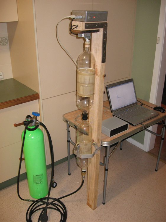
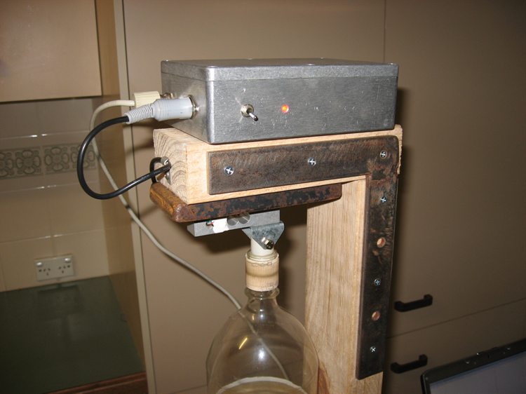
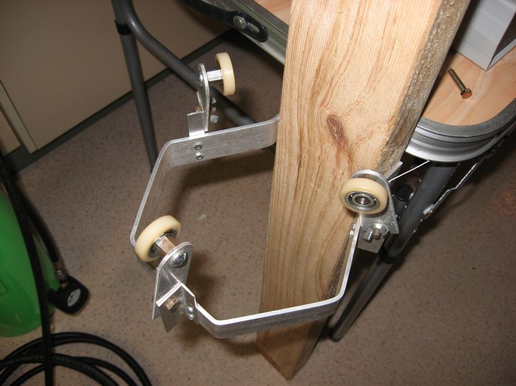
of up to around 600N. Test Stand
At the top of the test stand the load
cell is bolted to a heavy steel plate which
in turn is bolted to the stand. Above that
is the load cell amplifier. The entire
rocket is just suspended from the load cell.
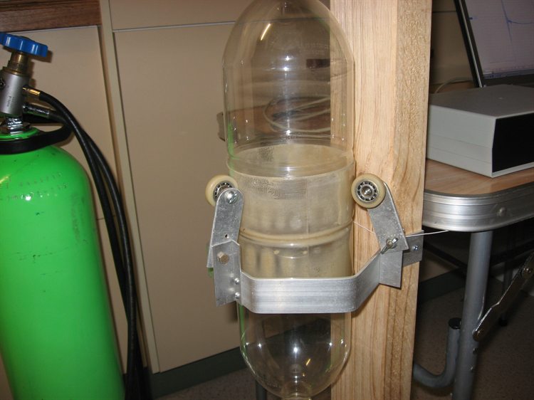
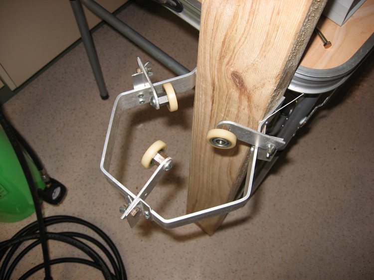
The arrangement at the bottom of the test
stand stops the rocket moving side to side
when thrusting. It consists of 3 adjustable
wheels on ball bearings that allow them to
be brought closer together for narrower
rockets and further apart for wider
rockets. The rocket only lightly touches
these (a few mm clearance) so there is
essentially no friction between them and the
rocket during the test.
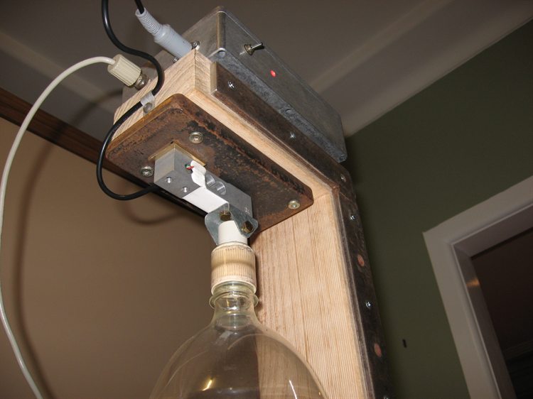
The rocket under test can be quickly
disconnected from the load cell with the
single pin that goes through the
bracket connected to the load cell. This
lets us take the rocket off, fill it with
water and re-attach it back to the load
cell.
The release mechanism
consists of a brass Gardena mechanism with
the spring removed and rubber bands are used
to provide a retracting force. We added a
non-return valve inside the release head as
well as a hose quick connect adaptor to the
bottom. We use a thick piece of plastic with
a string attached wedged under the collar.
To release the nozzle we simply pull on the
string and the whole mechanism falls away.
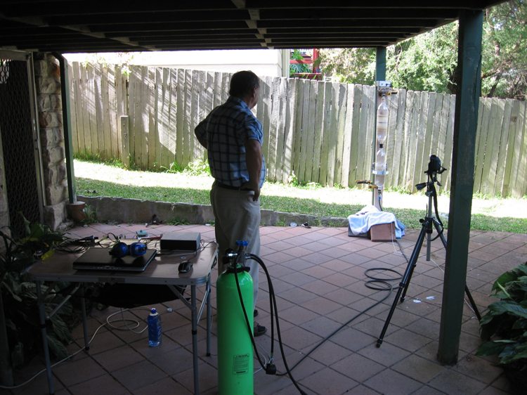
First Tests
We ran 4 thrust tests
yesterday
with different nozzles
on the new test stand. The tests were un-calibrated as we wanted to see what the
overall performance was.
We also set the amplifier
gain for the range
of thrusts we were
interested in.
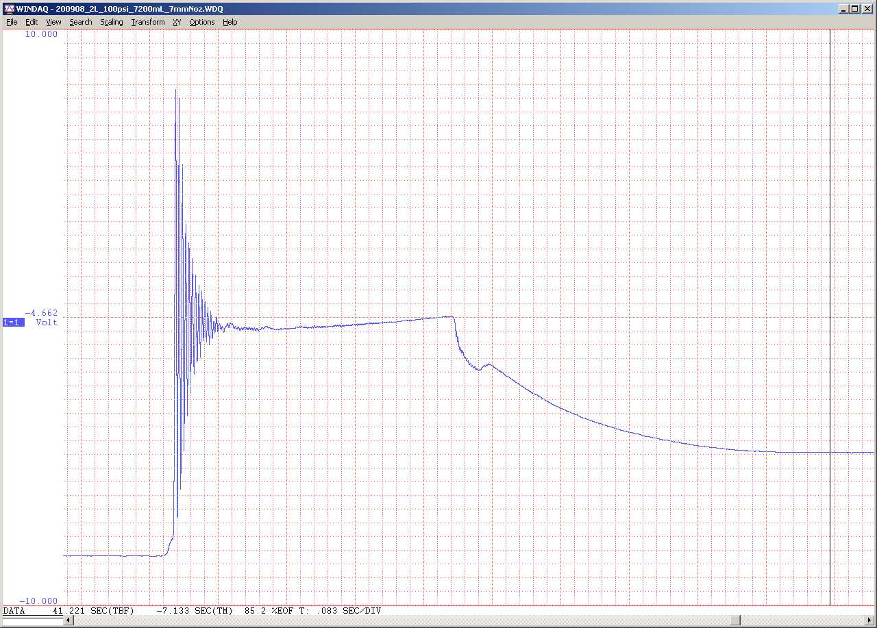
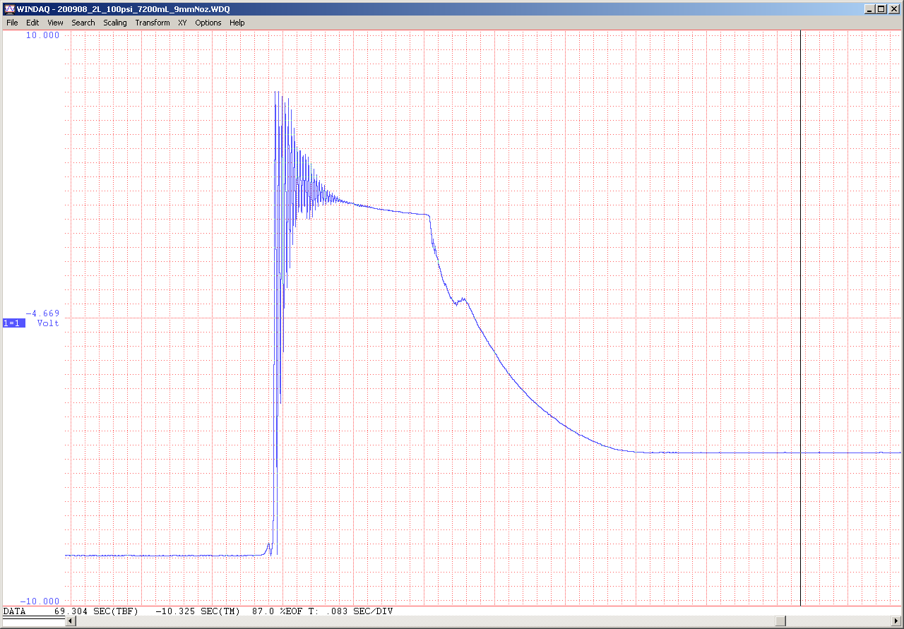
Here is an example of
the raw data captured for both 7mm and 9mm
nozzles at 100psi. There were 2 liters of
water in the 7.2L rocket. Sample rate was
240 Hz.
7mm nozzle thrust curve
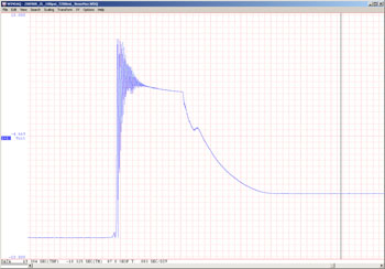
9mm nozzle thrust curve
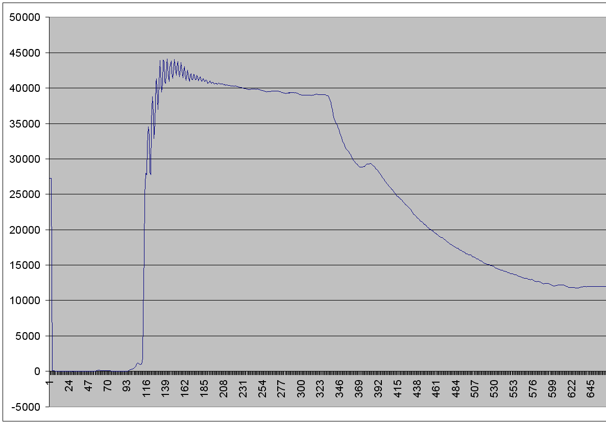
After bringing the data
into Excel, I corrected the offset and ran a
6 sample averaging window on the data to
reduce the ringing seen initially. The data
will be cleaned up further as we incorporate
the linearity curve of the load cell, and
average the data over multiple runs.
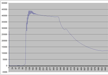
9mm nozzle thrust curve
filtered in Excel
The initial ringing is
caused by the initial launch pulse from the
rocket hanging to pushing upwards. It is not
too much of a problem as it can easily be
filtered out. The
pre launch
zero reading
represents the weight of the entire rocket
including water. At the end of the thrust
curve the zero level is higher because the rocket
is lighter. To get the
useful thrust we
essentially draw a horizontal line from the
end level to the start of the thrust curve
and only count what is above that since that
is the actual thrust component that
contributes to the
upward acceleration
of the rocket. The thrust
value under that line is the thrust that
just lifts the rocket off the ground
balancing gravity. The change in weight
of the rocket is non-linear due to the shape
of the bottle and the decreasing pressure.
We will leave data
analysis for another update once everything
is calibrated. In the diagrams above the
thrust can be approximated from the values
as the difference between the initial zero
level and final zero level is the weight of
the water = 2Kg. = 19.6N.
Overall everything went really well and I am
looking forward to doing the actual tests.
The total cost of the test stand not
including the laptop has been about AUD$230.
References
Other sources of load
cells, amplifiers and loggers we looked at:
|