Each flight log entry usually
represents a launch or test day, and describes the
events that took place.
Click on an image to view a larger image, and
click the
browser's BACK button to return back to the
page.
Day 85 - MicroLab - Mercury Switch Experiment
Date:10th
January 2010
Location:Doonside, NSW, Australia
Conditions:Hot (35C) with clear skies and
light breeze. 5km/h early increasing to
~20km/h later.
Team Members at Event: PK, GK,
Paul K, John K and Jordan K.
This week we did a couple of different
water rocket experiments. One
involved the first MicroLab payload flights
and the other a flight test of a new lighter parachute deployment mechanism. We also flew
Paul's 2-stage pyro rocket successfully
after the last crash. Since it's a bit of a
long write-up I'll only cover the mercury
switch experiment here, and do the deploy
mechanism and full flight day report as a
separate page.
MicroLab - Mercury switch
experiment
These MicroLab flights were designed to
demonstrate what happens on board a rocket
during flight. As many people start out
designing their first parachute deployment
mechanisms they sometimes base them on
incorrect assumptions about a rockets'
flight characteristics.
A very common question we get asked all
the time: "Why not put a mercury
switch on the rocket that will be able to
detect when the rocket tips over at apogee?"
This is a very reasonable question since a
system designed on this principle can work
very well on the ground. This MicroLab
experiment shows what actually happens to mercury
switches in flight.
Experiment Setup
A small digital video camera is
arranged to look through a lens at a set
of three vertically oriented mercury
switches. Two are mounted normally as would
be expected and the
other is mounted upside down. Switches #1
and #3 are identical (5mm diameter), while #2 is
larger. (6mm diameter).
They are each wired
to a separate LED so it's possible to see when
in flight they actually activate. There is
a white LED light source so the mercury
can be clearly seen. There is also a
barometric logging altimeter (Z-log) mounted on
the side to correlate the event timing
vs. altitude and speed. The payload is
powered by a lithium 6V battery (2 x
CR123A). The camera has it's own built-in power
source.
The launch is video taped from the
ground in order to get a reference of the
rocket's attitude in relation to the flight
time line.
Parachute deployment is controlled
independently by an electronic timer that is
triggered at the time of
launch. The deploy delay is set to initiate
the parachute deployment at apogee so that
the rocket would travel a certain distance
past apogee as it takes 2-3 seconds for the
parachute to fully open. This allowed us to
observe what happens to the mercury prior,
during and just after apogee.
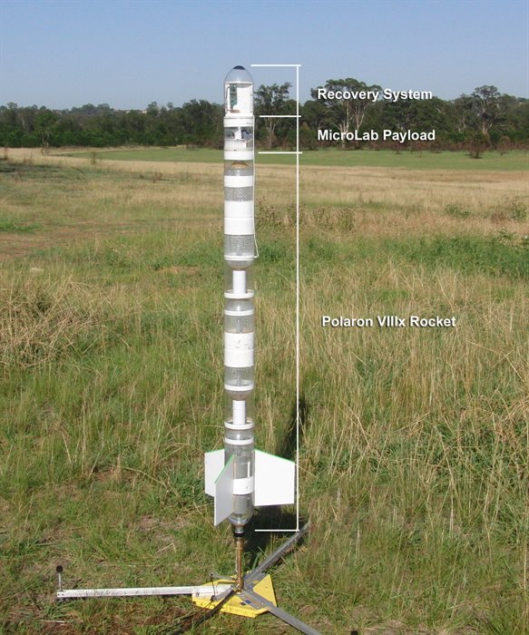
The MicroLab is attached to the top of
the Polaron VIIIx rocket with the following
parameters:
Parameter
Value
Capacity
9.8 L
Nozzle
15 mm
Launch Tube
15 mm (1200mm long)
Launch pressure
110 psi (7.6 bar)
Water
2.6L
Dry weight
1080 grams (including MicroLab = 178
grams )
Diameter
110 mm
Length
1750 mm
Deploy delay
5.2 sec
Recovery
Side deployment using FC
V1.6,
1.2m parachute
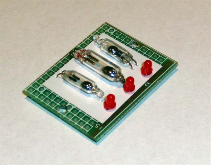
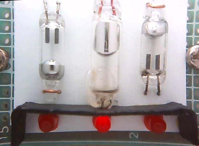
The experiment consists of 3
mercury switches wired to
separate LEDs.
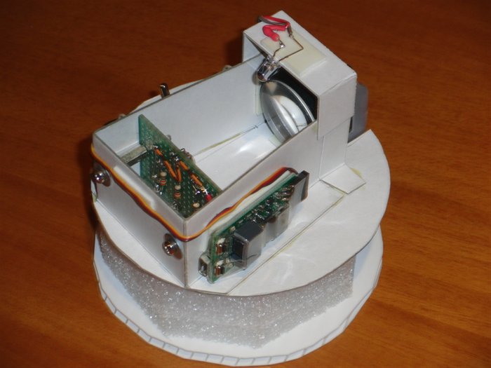
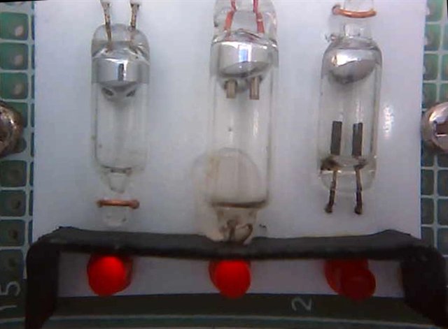
Back view of the experiment
showing the various components
Front view of the experiment
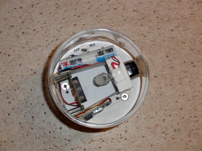
MicroLab mounted inside the
payload bay. Note the addition
of a light diffuser for the
light source LED as well as a
light shield for the activation LEDs
Payload ready to be attached
to the rocket.
Rocket configuration for the
experimental flights. The recovery system is
mounted on top of the payload and is powered independently from a 9V
battery.
Results
The experiment was flown two times on the
day within 30 minutes of each other. The
event timelines below were reconstructed
from the onboard and ground videos as well
as the altimeter data. The annotated
altimeter plots show when events took place.
Flight #1 Timeline
Time
Event
T
0
Launch
T+
0.24s
End of launch
tube reached
T+
0.64s
Start Air Pulse
T+
0.70s
Peak velocity
T+
1.28s
Switch #3
activates
T+
5.10s
Apogee 377' (
115 m )
T+
5.20s
Deployment servo
starts motion
T+
5.68s
End servo
motion - parachute ejected.
T+
6.64s
Switch #2
activates
T+
8.04s
Switch #1
activates
T+
8.24s
Parachute fully
open
T+
30.28s
Landing
Flight #1 - Timeline Events
Flight #1 - Annotated
Altimeter Plot
T+
0.24s - As the rocket clears the
launch tube there is a small
jolt on the rocket causing the
mercury to jump briefly.
As the rocket continues to
accelerate the mercury bead is
flattened and pushed into the
little pocket at the bottom of
the switch.
Upon burnout the mercury
either flies up (#3) or shows a
significant bulge on the top surface
(#1 & #2) The mercury pops
out of the little pocket again.
T+
6.64s As the parachute is
ejected it starts to exert a
drag force on the rocket and
switch #2 activates.
T+
8.04s The parachute is now fully
open and with the increased drag
all the switches are activated.
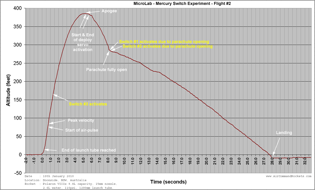
Flight #2 Timeline
Time
Event
T 0
Launch
T+ 0.24s
End of launch
tube reached
T+ 0.64s
Start Air Pulse
T+ 0.64s
Peak velocity
T+ 1.28s
Switch #3
activates
T+ 5.20s
Apogee 385' (
117m )
T+ 5.28s
Deployment servo
starts motion
T+ 5.75s
End servo
motion - parachute ejected.
T+ 7.96s
Switch #2
activates
T+ 7.96s
Switch #1
activates
T+ 8.28s
Parachute fully
open
T+ 27.92s
Landing
Flight #2 - Timeline
Events
Flight #2 - Annotated
Altimeter Plot
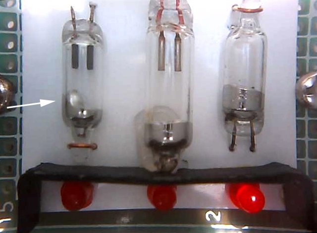
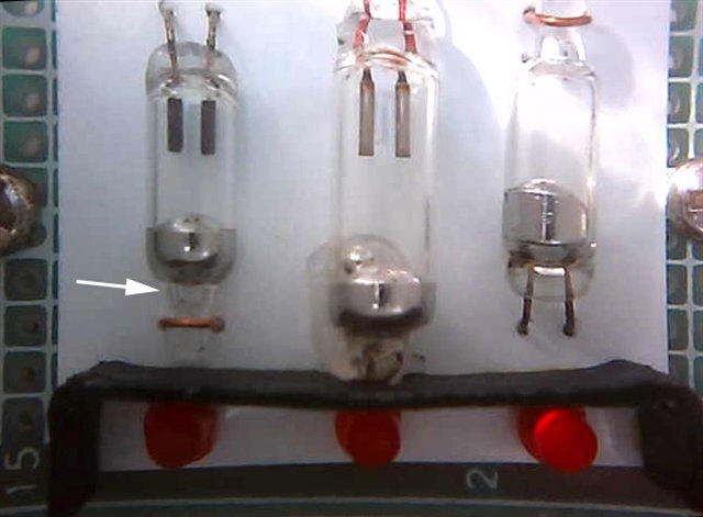
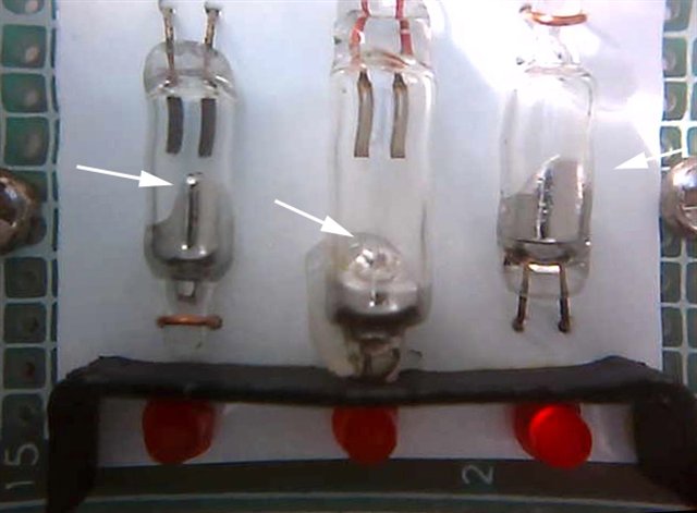
Rocket at rest on the launch
pad. Notice how the mercury's
surface tension keeps it from
the small pocket.
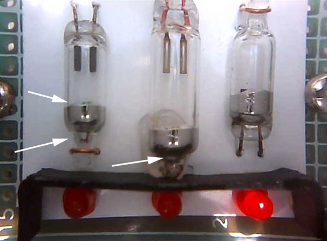
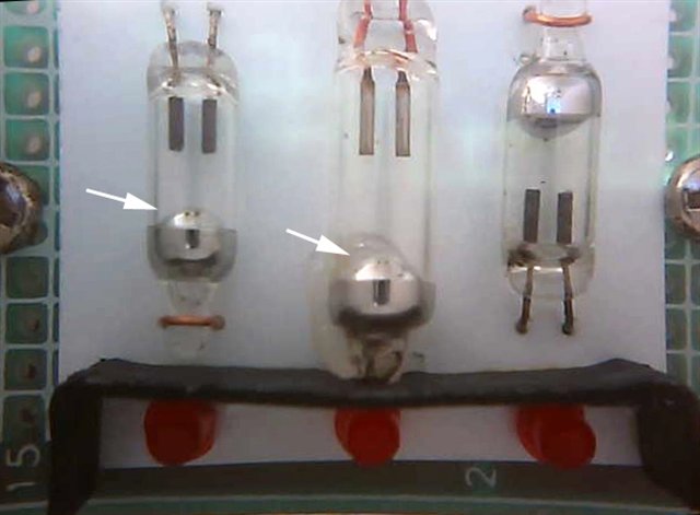
During acceleration the
mercury is pushed into the
pocket. Here the rocket has just
cleared the launch tube and the
jolt again causes the mercury to
splash.
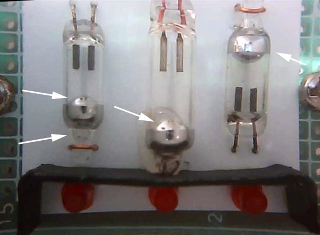
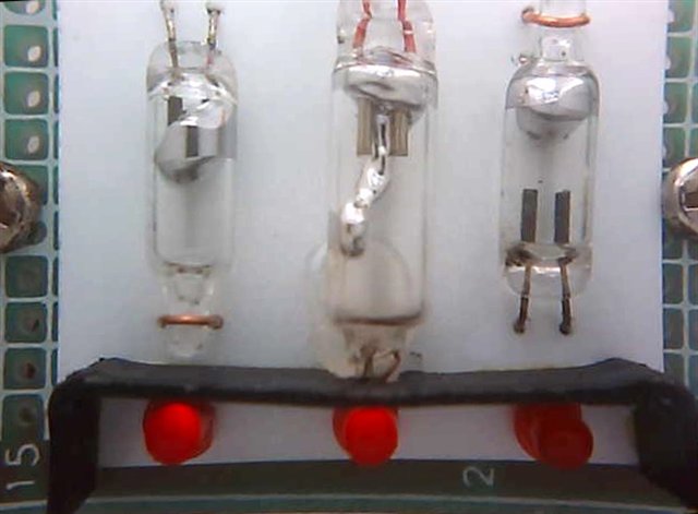
Deceleration after burnout
causes a bigger bulge on the
surface. (#1 & #2). Switch #3
flies up again.
Mercury splashing around as
the parachute opens.
In the video below we have combined the
ground and on-board videos. They are both shown in real
time as well as slow motion. An animated altimeter plot is also
included that shows the rocket's altitude
during the flight.
Video showing the
mercury switch behaviour in relation
to the rocket trajectory.
(Best viewed in HD -
click the HD button so it turns red)
Conclusions / Analysis
The video from both flights showed very
similar mercury switch behaviour.
Switch #3 showed the kind of behaviour
one
would typically expect during flight. It activated soon after
burnout and peak velocity. This happens
because air drag on the rocket causes it
to undergo -ve acceleration. There is no
air drag on the mercury bead and so it's
inertia carries it forward.
However, Switch #1 and #2 behaved quite
differently to what was expected. Why did the mercury not rise
like in switch #3? I can only assume that
it's either one of two things or both. a) The
adhesion forces/friction between the mercury and
the glass surface were higher than the
deceleration force. b) There may be a small
vacuum produced behind the
mercury.
The simulator predicted a deceleration of
around -0.3G due to drag at burnout, but
this would have reduced to near zero as the air
speed dropped near apogee and the rocket
experienced less drag.
It appears that switch #3 behaved as
expected because of the electrical
contacts were inside the mercury bead.
The mercury's surface tension would have
helped to push the contacts out and get the bead moving away from
the contacts when the small deceleration
force was applied.
No switch on both flights showed
any sign of activation as the rocket
passed through apogee. Switch #2 on
flight #1 activated somewhat earlier
than switch #1 but this was due to the drag of the
not yet fully open parachute. Switch #3
remained deactivated until the parachute
fully opened.
A mercury switch cannot be reliably
used to detect apogee. If a mercury
switch is used to detect burn out,
careful attention must be paid to its
orientation and ensuring the
deceleration forces are sufficient to
activate it.
Other Observations
If you look carefully there is a
little jump in the mercury just as the
rocket clears the launch tube. This
could potentially cause a false trigger.
During acceleration, the mercury
fills the little pocket at the bottom of
the switch. (see switch #1 and #2) When
acceleration stops the mercury pops out
again but the mercury does not float
upwards. The mercury does not fill this
pocket normally due to its high surface
tension.