 |
 |
|
|
last updated: 9th November 2024 - Day 236 - Launch Tubes #2 |
|
|
|
Splicing Bottles AS#5 |
|
#235 - Coming Soon |
|
#234 - Coming Soon |
|
#233 - Coming Soon |
|
#232 - Coming Soon |
|
#196 - Coming Soon |
|
#193 - Coming Soon |
|
#172 - Coming Soon |
|
|
| FLIGHT LOG | |||||||||||||||||||||||||||||||||||||||||||||||||||||||||||||||||||||||||||||||||||||||||||||||||||||||||||||||||||||||||||||||||||||||||||||||
|---|---|---|---|---|---|---|---|---|---|---|---|---|---|---|---|---|---|---|---|---|---|---|---|---|---|---|---|---|---|---|---|---|---|---|---|---|---|---|---|---|---|---|---|---|---|---|---|---|---|---|---|---|---|---|---|---|---|---|---|---|---|---|---|---|---|---|---|---|---|---|---|---|---|---|---|---|---|---|---|---|---|---|---|---|---|---|---|---|---|---|---|---|---|---|---|---|---|---|---|---|---|---|---|---|---|---|---|---|---|---|---|---|---|---|---|---|---|---|---|---|---|---|---|---|---|---|---|---|---|---|---|---|---|---|---|---|---|---|---|---|---|---|---|
|
|||||||||||||||||||||||||||||||||||||||||||||||||||||||||||||||||||||||||||||||||||||||||||||||||||||||||||||||||||||||||||||||||||||||||||||||
| Day 138 - Dual Thrust Rocket | |||||||||||||||||||||||||||||||||||||||||||||||||||||||||||||||||||||||||||||||||||||||||||||||||||||||||||||||||||||||||||||||||||||||||||||||
|
Date:
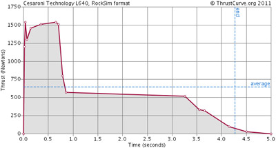
30th November 2013 It's been a while since the last update. There have been three total fire bans in Sydney during the past couple of months so the NSWRA launches had been cancelled. I've also had to put development on hold for a few weeks while my wife was in hospital and then at home recovering. Even though we weren't launching there have been plenty of things keeping us busy. This week we flew a small dual thrust rocket a number of times in different configurations. Dual ThrustThe main idea behind a dual thrust rocket is to give a rocket a large acceleration on launch and then a longer prolonged burn for a sustained flight. This concept has been around for many years. There are many examples of this in the pyro rocket world not only in HPR but also in weapons systems. (See reference section) It is similar to how a T-nozzle works in water rockets, although the T-nozzle only has a large nozzle during the launch tube phase. Here is a dual thrust water rocket example that uses a sliding nozzle that allows for more water to be ejected through the large nozzle before switching to the smaller nozzle. http://www.sonic.net/~rci/rocket/os2.html. A typical thrust curve for a Dual Thrust rocket is shown below. (In this example it is CTI L640) Image source: http://www.thrustcurve.org/simfilesearch.jsp?id=1619
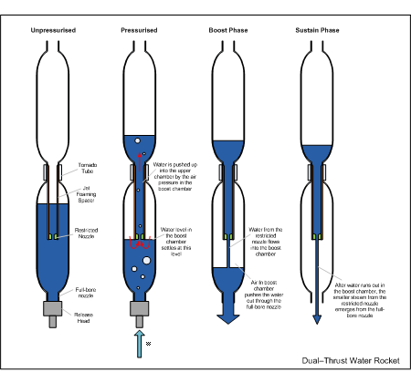
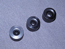
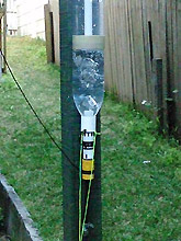
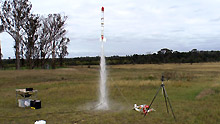
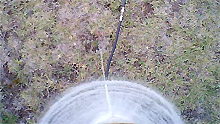
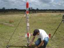
The implementation we used in our tests is just the Jet Foaming Spacer we have been using on our rockets. The difference is that when we normally use the jet foaming spacer the hole in the spacer is comparable to the size to of the hole in the nozzle. This ensures that the water doesn't drain from the main nozzle too quickly and allows the foam to form in the lower part of the rocket. The dual thrust rocket uses the opposite principle and makes the main nozzle large and the internal nozzle small. This allows the bottom bottle to drain very quickly giving the large initial boost, and at the same time the internal nozzle produces a much weaker but longer burn so that the rocket sustains the flight. The internal nozzle is simply directed out of the main nozzle. In this configuration the spacer is longer to create a bigger air pocket at the top of the boost chamber. The spacer also serves the same function as in the Jet foaming configuration which creates a constant size air gap at the top of the lowest bottle. So all you have to do is fill the rocket as normal and then when pressurised the water will sort itself out to the right levels in the top and bottom chambers. You can tune the system by varying the length of the bottom pressure chamber to increase or decrease volume for the boost phase. You can adjust the length of the spacer to change the water to air ratio and finally you can adjust the size of the internal nozzle to change the duration of the sustain phase. One added benefit is that for the sustain burn, the water is stored a lot further up the rocket aiding in the rocket's stability. As we wanted to try several different configurations we made the internal nozzle swappable. We made 3, 5 and 7mm inserts for the inner nozzle. Simulations predicted that this kind of rocket is going to perform a little worse than a normal rocket with a large nozzle. A good opportunity to test the simulators. There have been similar full length tubes used in water rockets previously to try to mix the air and water for example Jelo's, Thunderrocket's and Todd's experiments: (http://wrocket.hampson.net.au/?p=1196) but the aim with the dual thrust rocket is not to mix the air and water. Static Tests(22 / 9 / 2013) Before launching this rocket we wanted to see what the entire system will do, so we fired it on the static test stand a couple of times. We had to make a couple of modifications to the stand to fire a full bore nozzle. We are using a sawn-off Clark cable-tie launcher to launch this rocket because the spacer gets in the way of a long launch tube. We suspended the release head so it would not impact the ground after release. With a full bore nozzle the release head gets ejected from the rocket at a good pace. We did not connect the rocket to the load cell this time. For these tests the rocket consisted of two 90mm spliced-pairs and a single bottle joined with tornado tubes giving a total capacity of around 5.45L. Test #1 We filled the rocket with 1.7L of water and used the 5mm insert for the inner nozzle. The lower chamber is divided into approximately 50:50 water to air ratio as this is what the simulator suggested. Generally the optimum water fill for boosters is a higher proportion of water when compared to normal rockets. This means that about 1L was in the boost chamber and about 0.7L in the upper chamber. We pressurised the rocket to 40psi and fired. We wanted to try a lower pressure first to see how the large bore nozzle release head behaves. Having the release head suspended meant that no damage was done.
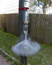
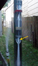
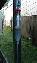
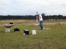
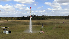
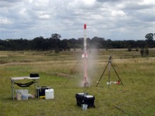
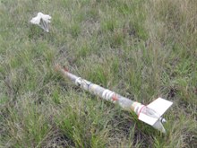
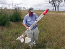
Observations The boost phase looked like it worked well except that some air mixed in as a result of the blow-through caused by the inner nozzle.The exhaust plume out of the main nozzle was quite turbulent. This is likely reducing the efficiency of the boost as air is being ejected before all the water is ejected. Ideally you would not want any air to mix with the water in the boost chamber. In the sustain phase the water stream was quite even and emerged from the main nozzle cleanly. Once the air pulse started the exhaust from the main nozzle became quite turbulent again, and a small amount of water was getting pushed up against the sides of the boost chamber. We have seen this before. The slow motion video showed that as the sustain phase air pulse started, it generated enough of a vacuum that it collapsed the lower bottle briefly. This is not too much of an issue though, but with fins fitted to that part of the rocket it may briefly move them in flight? Test #2 We repeated the experiment and this time fired the rocket at 110psi. Again the two thrust phases were clearly visible and the results were similar to the first test. The bottle again collapsed during the sustain air pulse phase. The tests showed that the dual thrust arrangement created the distinct two phase thrust but actual flight performance was still unknown. We had to wait a couple of months before we could test fly it. The following video shows these two tests. Launch dayAlthough it was a little windy on launch day, the wind was blowing away from the rocket eating trees and so there were no issues with launching. The first rocket was set up with a 5mm inner nozzle in the dual thrust configuration. We launched it at 120psi and you could see the quick boost up to speed and then a prolonged stream of water for the gentle sustained flight. The rocket didn't go very high, only around 253 feet. It was a very nice flight to watch though. We repeated the flight with 100mL less of water to make it lighter during launch and again the rocket performed similarly to the first flight but went up to 268'. We then replaced the inner nozzle with the 3mm insert and set the rocket up again. At 3mm the nozzle is less than 2% of the cross sectional area of the main nozzle. We used 1.6L of water in the rocket. The launch again was quite quick, but the sustain was very gentle and just kept the rocket moving up slowly. The air pulse from the sustained flight came quite late and near apogee. The rocket only reached 203'. This was definitely a fun one to watch. The rocket was stable after boost even with so much water still in it. For comparison we flew the same rocket @120psi with a standard configuration and a 9mm nozzle and the rocket went up to 373'. For the last launch of the day, we flew the dual thrust rocket again with the 3mm inner nozzle but pressurised to 125psi. The rocket flew the gentle sustain flight again this time to 219'. In all four dual thrust flights it was evident that the boost phase exhaust contained a lot of air which would have reduced the efficiency of the flight. When air escapes past the water then it's not being used to accelerate the remaining water out of the nozzle. ConclusionsAs can be seen from the results, not all experiments lead to better performance. The simulators were right in that the rocket would not perform as well as a regular rocket, and in fact they were a little optimistic as the rocket flew lower than expected. Some of this may be attributed to the loss of pressure in the booster chamber due to the blow-through effect. One option to solve the blow-through is by putting the nozzle a lot further down in the water and then adding a small non-return valve half way up the spacer. This should allow the water to equalize up to the valve, but once launched keep the water inside the spacer. This was a fun experiment to see what would happen in flight with this configuration. While this particular configuration didn't lead to better performance, it does offer a different flight profile for a number of in-flight experiments. This experiment should be repeated with higher pressures. The rocket also remained stable throughout the entire flight despite a considerable amount of water in the rocket during a major part of it. Here is a highlights video from the day. If you have questions or comments about the dual thrust experiments please jump to the bottom of the page.
References
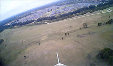
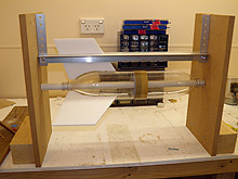
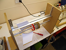
Other DevelopmentsThere have been a few more developments and events that have happened in the past couple of months. Fin Alignment JigThe last few launches have used older fin-cans that aren't terribly well aligned and as a result we've had a few spinning on-board videos. We made up a simple fin jig to make a new fin-can that is hopefully better aligned. We'll make up a few more fin-cans and retire the old ones. We flew these new fin cans this weekend and although they didn't completely stop the roll they have significantly reduced it. Some of the roll may have been due to other protrusions on the rocket like the camera and parachute deployment system.
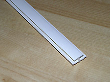
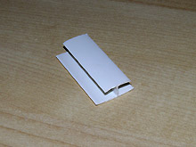
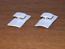
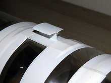
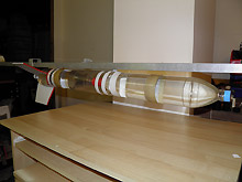
Both sets of fins are removable from the pressure chamber. PVC Rail ButtonsAfter testing the PET rail buttons a couple of months ago, we weren't quite happy with their strength. This time we made the rail buttons in the same profile from a PVC extrusion used to join Hardiflex panels. These are a lot stronger and hold the rocket securely under larger loads. The small profile also means they are more aerodynamic than our normal machined rail buttons. Each weighs 1.5 grams. We heat the bottom wider section in hot water and then form it on a roller to the bottle profile. The rail button is just attached with electrical tape to the side of the rocket. At 2.4m length for the extrusion, you can make about 50 rail buttons at a cost of a few cents each. WARAausKIEL also uses a similar rail button system but built around an plastic I beam. We also did a load test on the rail buttons by filling a pair of spliced-pairs completely with water and suspending them horizontally by the guide rail. This gave a total weight hanging off the two buttons of 4.2Kg (9.2 lbs). That's strong enough for our purposes. We test flew these rail buttons on one of the rockets this weekend. Polaron G2Development
has continued on this rocket over the last few weeks.
We've been focusing on getting the
boosters made and attached. You Have Been Warned - Series 2In December last year I was contacted by October Films in the UK working on a Discovery Channel show called "You have been warned - Series 2" about using one of our YouTube clips. Over the last few months they have asked many technical questions as I think they will have a presenter describing how our 2-stage water rocket works. I've also sent them copies of the clip without any of the text overlays, as I believe they want to add their own. I don't know how the final presentation/clip will look, so it should be interesting. I recently received a tentative date for when the episode should air in Oz. Episode 11: Backyard Boffins (provisional date 30 Dec 2013) In Australia:
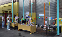
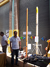
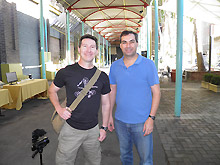
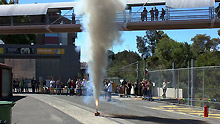
http://www.discoverychannel.com.au/shows/you-have-been-warned/ I believe the show is also called "Outrageous Acts of science" in the US, but I am not sure it is the same content or not. Nozzles ArticleWe have added an article on nozzles that describes some of the differences between the nozzles commonly in use. Powerhouse Museum Mini Maker FaireLast week as a part of the NSW Rocketry Association we were at the Mini Maker Faire at the Powerhouse Museum. We had a similar setup to what we normally have at the Macquarie University Astronomy open nights, There was a good turnout of people and it was fascinating to see what other Makers do in their spare time. We also managed to static fire a number of G class motors which are always fun to watch because they are loud and produce a lot of flame & smoke. It was also great to catch up with Dave Jones from his excellent EEVblog. Dave and I worked together for a short time back in 1994 and this was the first time since then that we had met up again. More photos here: http://www.nswrocketry.org.au/gallery/OtherEvents/2013_PowerhouseMuseum/PowerhouseMuseum_01.html
Flight Details
|
|||||||||||||||||||||||||||||||||||||||||||||||||||||||||||||||||||||||||||||||||||||||||||||||||||||||||||||||||||||||||||||||||||||||||||||||
<< Previous Back to Top Next >>
