Each flight log entry usually
represents a launch or test day, and describes the
events that took place.
Click on an image to view a larger image, and
click the
browser's BACK button to return back to the
page.
Day 77 - Acceleron V - development
progress
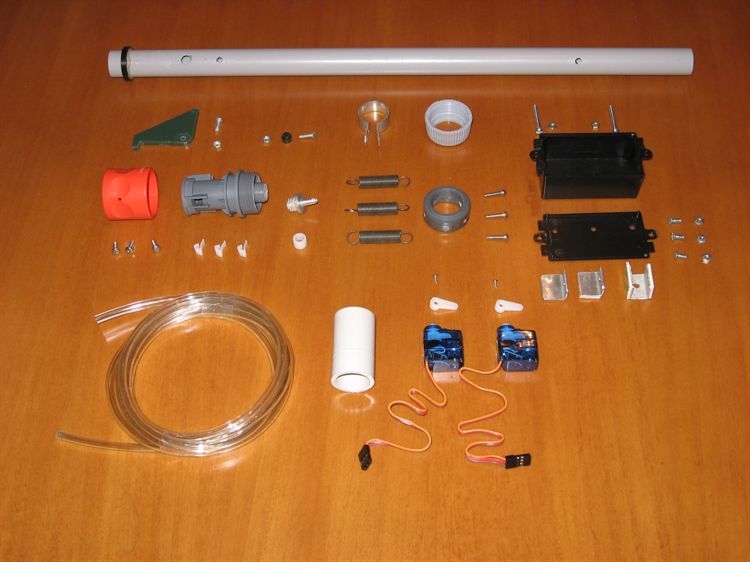
Baseplate components are a mix of steel,
aluminium, PVC, carbon fiber, rubber and nylon.
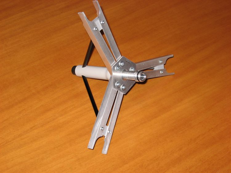
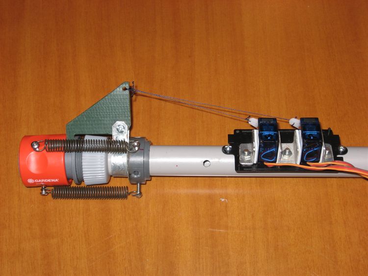
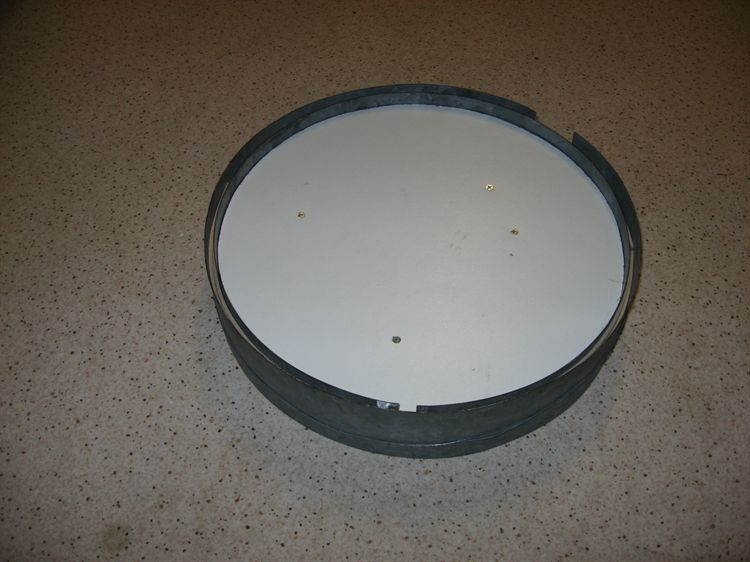
Bottom view of the assembled baseplate. The
central 'nozzle' holds down the entire rocket.
Top view of the baseplate. The CF struts are
epoxied in place.
Testing the pulling force of the servos. The
thread has now been replaced with nylon coated
steel wire.
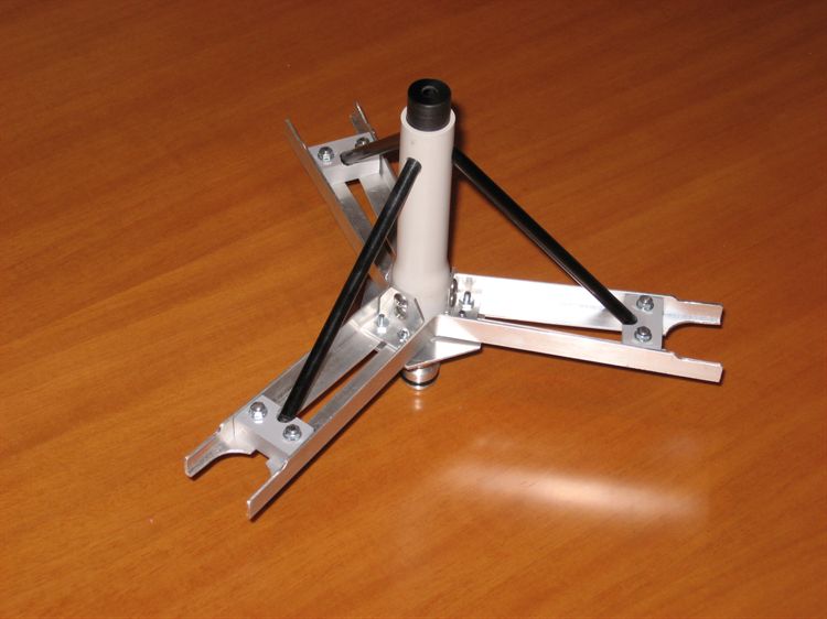
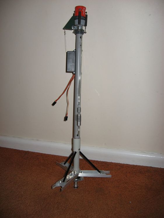
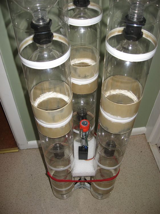
Top view of the fully assembled baseplate
and staging mechanism.
The servo box protects the servos from the
water spray.
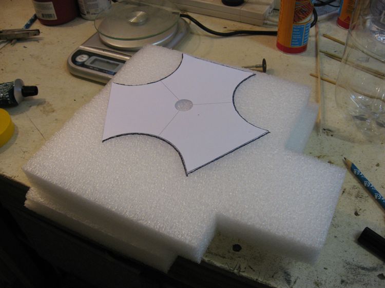
Cutting out the centering foam brace. This
brace keeps the stager centered between the
booster segments.
Side view.
Pressure testing the staging mechanism. the
tests were carried out at 130psi.
We tested the two servos individually at
full pressure. A dummy sustainer is fitted to
the stager.
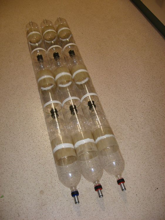
Testing the main booster bottles.
3 Booster segments each about 11L in
capacity. They are connected with Tornado
couplings.
Here the boosters are fitted to the staging
mechanism and baseplate.
A closer view of the foam brace.
The top foam brace is only temporary until
the actual ring brace is finished.
Looking down at the stager.
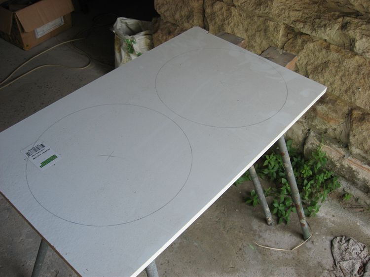
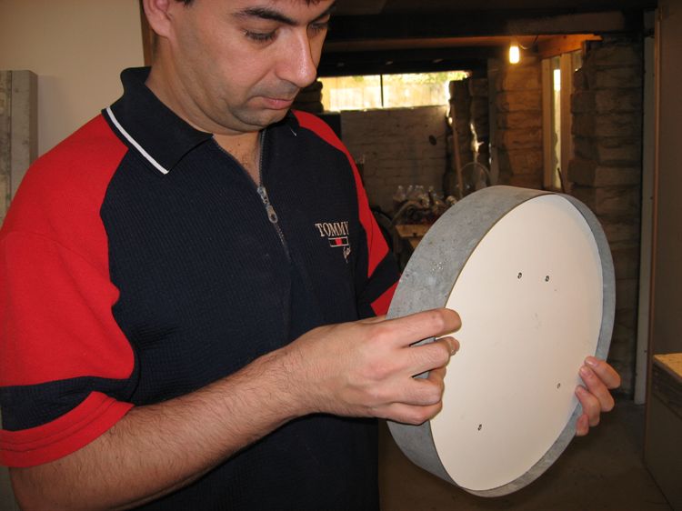
The ring brace is being made from laminated
balsa wood wrapped in fiberglass.
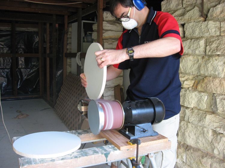
Cutting out the forming mold.
The ring is 320mm in diameter.
Smoothing the edges of the mold.
We wrapped a steel plate around the mold.
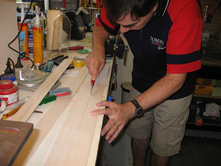
Cutting up the balsa.
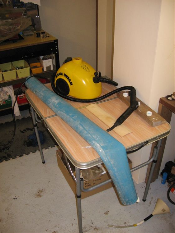
A less than successful steam box. The
PVC pipe simply softened.
A piece of steel drain pipe worked a lot
better. Here it is being filled with steam. The
ends are plugged only with cloth to prevent the
drainpipe from exploding.
Another steel plate on the outside forms the
rest of the mold here the balsa is drying before
it is glued.
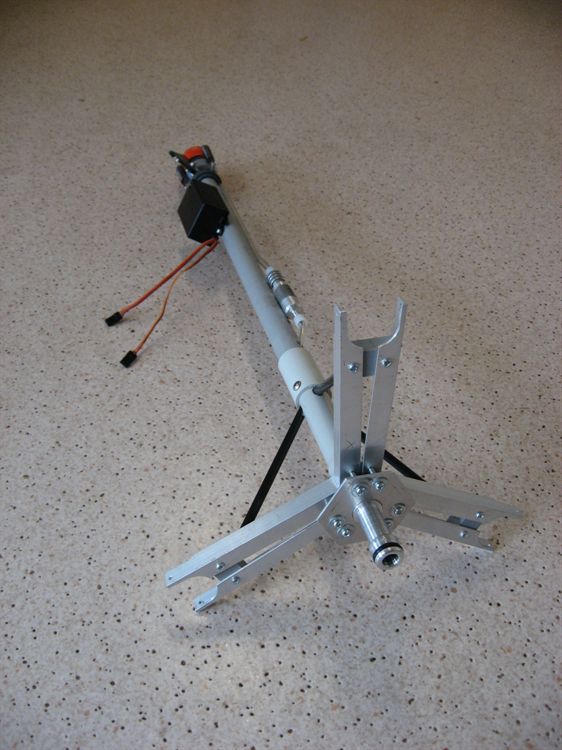
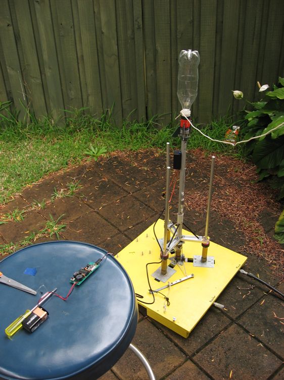
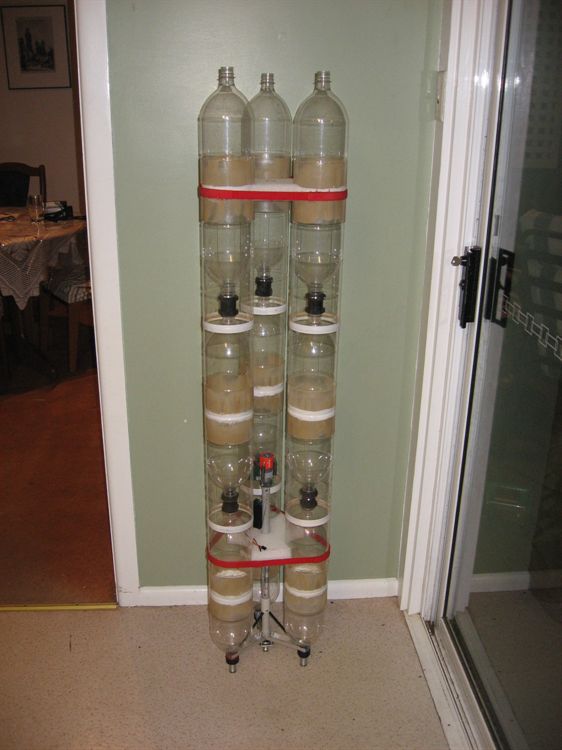
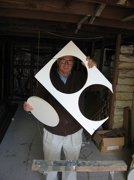
A test assembly of what the 2 stage rocket
will look like.
Date:27th
April 2009
Location:Workshop
Conditions:Pleasant
Team Members at Event:PK and
GK
Acceleron V
We have been focusing on the development
of Acceleron V over the past few weeks.
Progress has been steady but good. We are
now trying to get it finished by the next
NSWRA launch day. We were going to be close
for this weekend, but since the launch has
been delayed at least a week we should now
be able to finish it by then.
What's done:
Base plate is complete
Staging mechanism is complete
All bottles have been spliced and
have had their necks reinforced.
Staging mechanism has been pressure
tested to full operational pressure.
Inter-bottle spacer rings have been
made.
What's left to do:
Both parachute deployment mechanisms
All the wiring between flight
computers, stager, pressure switch needs
to be done.
Mount cameras and altimeters in both
booster and sustainer
Run simulations and configure flight
computers accordingly, and figure out
how much water is needed.
Top support bracket that holds the
booster segments together. As of this
weekend this is partly complete.
Make and attach fins.
Pressure test all the bottles to
full operational pressure.
Test the strength of the baseplate
at full pressure.
We are still debating
what to do about the guide rail, or if we
will use one at all. Acceleron has always
only used a pair of short ones.
The most amount of time
has been spent putting together the
baseplate and staging mechanisms. One of the
goals was to reduce it's overall weight.
Acceleron IV had the baseplate, support tube
and staging mechanism weigh in at 635 grams
which was essentially dead weight on the
booster. The new baseplate and staging
mechanism only weigh 372 grams so close to
half the weight has been saved.
Baseplate
The baseplate is
responsible for linking the three booster
segments together as well as providing a
common hold-down point for the entire
booster. It supports the full weight of the
sustainer during acceleration. We had to use
aluminium for the main components due to the
forces involved in this part of the rocket.
The central nozzle (its not really a nozzle)
needs to hold down around 80kg (175 lbs)
when the rocket is fully pressurized. The
entire nozzle (and rocket) is only held down
by three stainless steel ball bearings in
the brass release head. Plastic components
here would not be able to hold that much
force.
The central nozzle also
supplies air to the sustainer via a
non-return valve.
The horizontal brackets
are also made of aluminium to provide enough
strength for each booster segment. The
diagonal struts are made from 6mm carbon
fiber tubing and are anchored in PVC blocks
near the nozzles of each booster. The
central support pipe is made from 20mm PVC
tubing. The struts are all epoxied in place. A
plastic plug was made for the top of the PVC
pipe that contained the epoxy while curing and provided a
hole to let the sustainer air supply to pass
through. The top of the plug helps to center
the main PVC pipe leading to the staging
mechanism.
After test assembling
the base plate in the launcher with the
actual booster segments fitted with their
nozzles we discovered that the central
mechanism just couldn't go down far enough
to properly lock into the mechanism. Not
wanting to machine up a whole new central
nozzle, we decided to put a thick plastic
washer between it and the base plate. Using
longer screws to hold it all in place was
enough to resolve the issue.
The other issue we had
was while trying to fit the hose on the end
of this central nozzle we found it a little
difficult, so we decided to machine down the
hose connector a little bit to make it
easier. While machining the small thin tube
caught on the knife and unceremoniously
bent, and was damaged. While trying to
straighten it, as suspected it snapped off.
Dad came to the rescue and machined off what
was left, then proceeded to cut a thread
into the top of the nozzle and made a new separate
hose connector component that simply screwed
into the end. We epoxied it in place and all
was good again.
Staging Mechanism
The staging mechanism
is based on a modified plastic Gardena quick
release connector. The normal hose connection
has been removed and replaced with an
aluminium connector machined to fit the thin
tubing we are using. This has been epoxied
into the central hole. The spring has also
been removed from the collar. 3 screws are
fitted to the collar to hook the springs on
which pull the collar back.
We are using springs on the collar this time
rather than rubber bands to give more
release force
and also to prevent the problem with rubber
perishing when it stays stretched for a long
time.
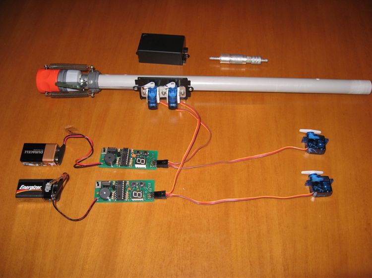
The staging mechanism
uses two servo motors for redundancy. They
are separately connected to the staging
mechanism's release arm by tiger tail (nylon
coated braided steel wire) and crimped to
prevent knots untying and strings
stretching.
The servos are mounted
inside the servo box to protect them from
the spray. The steel wire is fed through a
hole on the side.
A foam brace below the
servo box is used to support the boosters as
well as keeping the mechanism centered.
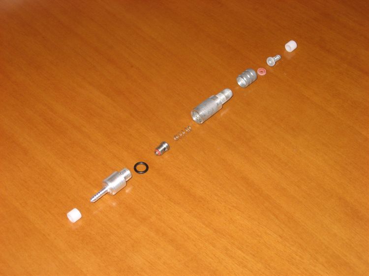
Non-return valve
The air supply to the
sustainer passes through the central nozzle and
through the non-return valve. The non-return
valve is one adapted from the previous
Acceleron rocket. Originally the non-return
valve was going to be mounted inside the
main PVC pipe, but mounting it on the
outside meant we could more easily service
it and check it for leaks. The air supply
plastic tubing has a 3mm ID that we have
tested to 180psi for 2 minutes. This tubing
came from Clark Rubber.
Testing
We performed a couple
of tests this weekend to check for leaks and
if the servos can activate the staging
mechanism at full pressure. Gardena
connectors tend to tighten up under
pressure. The springs had enough force to
pull back the collar and release the
sustainer. We used a small 600ml bottle
completely filled with water as a dummy
sustainer. We tested each of the flight
computers separately connected to their
respective servo motors. We were very happy
when there were no leaks and the servos
worked as expected.
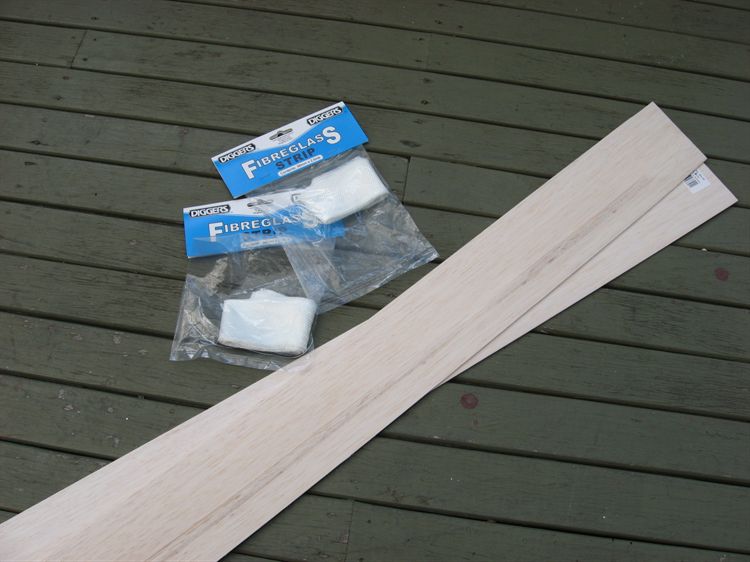
Ring Support Brace
The top support brace
holds the booster segments together while
giving clearance for the sustainer fins to
pass through it. It is being constructed from laminated balsa
wood wrapped in fiberglass. We spent the
weekend building the mold that is used for
forming the balsa to the right shape. The
mold simply consists of two disks of wood
separated by a couple of blocks. These disks
are then wrapped with a strip of sheet
metal, and screwed to the disks. The balsa
is simply bent around this and wrapped again
by a second strip of sheet metal to form the
other half of the mold. Tensioned wire holds
the whole thing together.
We looked at quite a
few woodworking websites on how to bend
wood. The almost universal approach was
using a steambox. There were plenty of
details on how to easily make a steam box
out of a length of PVC pipe.
We had a spare pipe on
hand so we plugged the ends with cloth to
prevent pressure build up. Fortunately we
had a one of those steam cleaners on hand
that generates lots of steam from a nozzle
and so we inserted that through one end. The
first attempt at making the steam box didn't
quite go according to plan. After setting it
all up and steam started building up the
pipe became very hot and then softened up
before drooping off the end of the table.
I'm not so sure this was the right kind of
PVC we were supposed to be using.
Attempt #2 was much
more successful when we switched to using a
piece of rectangular steel drain pipe. The
wood softened up nicely and allowed itself
to be bent around the mold. We are now
waiting for the balsa to fully dry before
gluing it together. When that is done it
will be wrapped with a couple of layers of
fiberglass to strengthen it further and
waterproof it.